00193733-02.pdf - 第62页
2 Assembly Instructions PCB Camera, Multicolor SIPLACE F5 HM SIPLACE F5 HM 2.6 Assembly Terminal panels and Illumination cable 05/2007 Edition 62 2.6.5 Inst alling th e "PCB Camera Bo ard, Modular" from the ass…
SIPLACE F5 HM 2 Assembly Instructions PCB Camera, Multicolor SIPLACE F5 HM
05/2007 Edition 2.6 Assembly Terminal panels and Illumination cable
61
: Use the table to determine whether the distance plate is required.
If yes, place the distance plate (see Abb. 2.6.6 -> 1) from the camera assembly kit on the ca-
mera’s assembly surface in the correct rotational position (this is determined on the basis of
the holes).
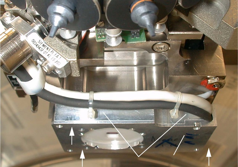
Abb. 2.6.7 Fastening the PCB Camera Multicolor (View from below, diagonally)
Key: 2
1.PCB camera Multicolor
2. Fasteners: 3 hex head cap screws M3 x 14 (captive)
3. 2 Cable ties
2
: Place the PCB camera Multicolor, including the distance plate, if applicable, in the correct po-
sition on the distance bolts (HS-50) or directly on the camera holder from below (S-25 HM).
: Use the 3 captive hex head cap screws M 3 x 14 to screw the camera to the camera holder.
: Fasten the cables with the two cable ties (see 2.6.7).
2
2
21
3
2 Assembly Instructions PCB Camera, Multicolor SIPLACE F5 HM SIPLACE F5 HM
2.6 Assembly Terminal panels and Illumination cable 05/2007 Edition
62
2.6.5 Installing the "PCB Camera Board, Modular" from the assembly kit
NOTE
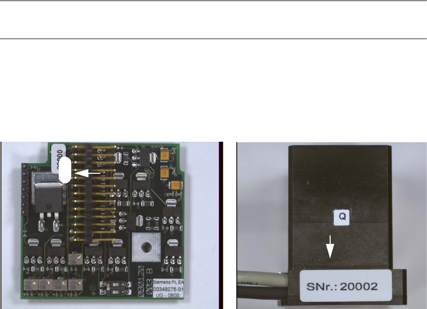
The "PCB camera board, modular", is attuned to the pertinent PCB camera Multicolor. 2
: Check the serial number of the PCB camera board, modular:
It must correspond to the number on the Multicolor PCB camera.
Per gantry this allocation must be maintained during installation.
The position of the number is shown in the following illustration.
Abb. 2.6.8 Check: Identical Serial Number on Modular PCB Camera Board and PCB Camera Multicolor
2
: Plug the "PCB camera board, modular" onto the "Vision board, modular" in the correct position,
as shown above.
The contact jack on the bottom of the PCB camera board must move all the way into the con-
nector of the vision board.
: It is necesssary, that you control the correct mounting position of the "Vision-Board modular".
20002
SIPLACE F5 HM 2 Assembly Instructions PCB Camera, Multicolor SIPLACE F5 HM
05/2007 Edition 2.6 Assembly Terminal panels and Illumination cable
63
2.6.6 Laying Cables, Plugging into PCB Camera Board and Vision Board
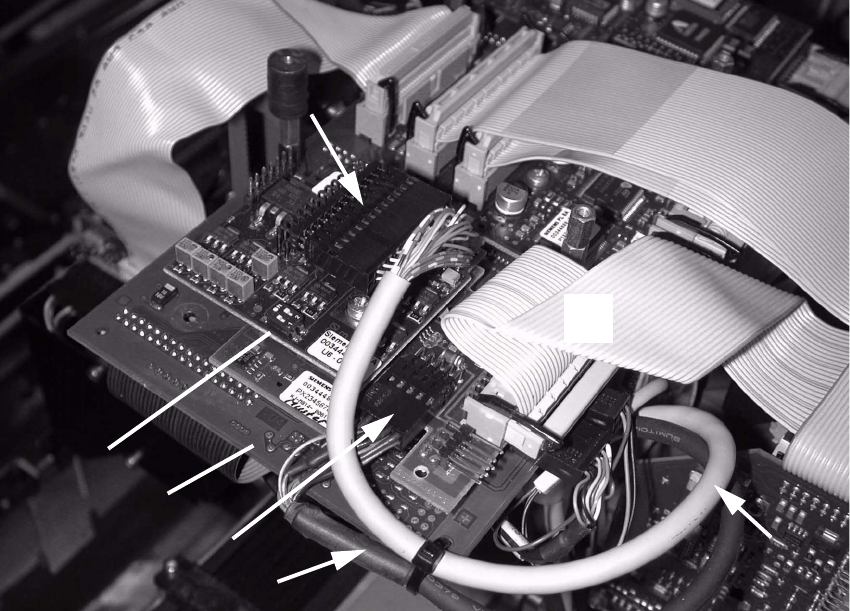
: Run the two cables from the PCB camera Multicolor up to the head PCBs (see Fig.).
: Plug the connectors of the PCB camera Multicolor into the "Vision board modular" and into the
"PCB camera, modular" located above it (Abb. 2.6.9).
Layout of the PCBs -> see Fig. 2.13.1 and Fig. 2.13.2.
Abb. 2.6.9 Plug In the Connectors of the PCB Camera Multicolor
Key: 2
1. Vision board, modular
2. Plug-type connector on X4: Cable "Camera" of PCB Camera Multicolor
3. PCB camera board, modular
4. Plug-type connector on X3: Cable "illumination" of PCB camera Multicolor
5. Correct cable layout: = above the PCB: See Abb. 2.6.10, NOTE
6. Cable "illumination" of PCB Camera Multicolor
2
2
2
2
4
3
1
5
2