00193733-02.pdf - 第67页
SIPLACE F5 HM 2 Assembly Instructions PCB Camera, Multicolor SIPLACE F5 HM 05/2007 Edition 2.6 Assembly Term inal pan els and Illumination cable 67 2.6.7 Assembling the Placemen t Head and the Machine : Place the cover p…
2 Assembly Instructions PCB Camera, Multicolor SIPLACE F5 HM SIPLACE F5 HM
2.6 Assembly Terminal panels and Illumination cable 05/2007 Edition
66
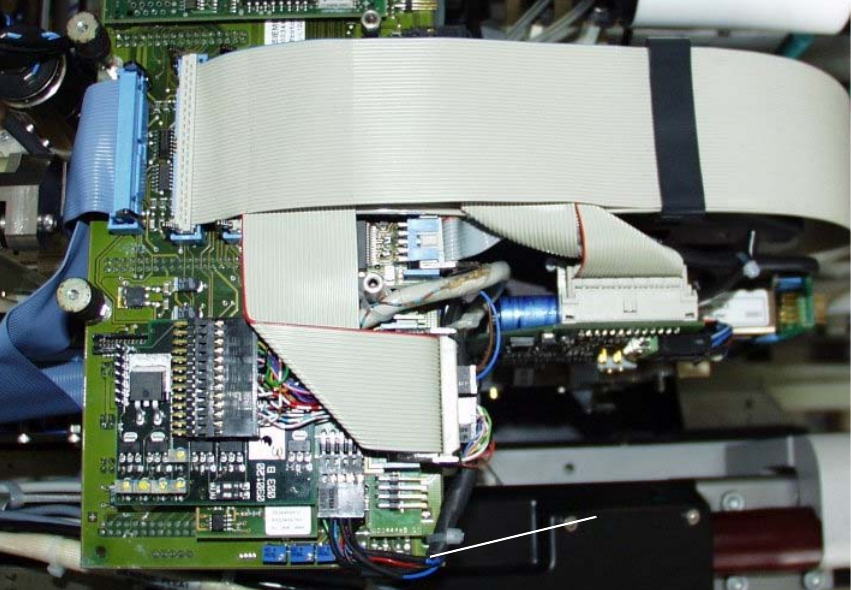
: In the 2nd step run the top ribbon cable down and plug it in (Abb. 2.6.11).
: Push the ribbon cable retaining clamp into the particular position shown.
: Make certain that all of the plug-in connections are secure.
Abb. 2.6.11 2nd Step while Laying Cable in the Area of the Head PCB
Key: 2
1. In connection with laying the "Camera cable", comply with the NOTE below the key to Abb.
2.6.10.
1
SIPLACE F5 HM 2 Assembly Instructions PCB Camera, Multicolor SIPLACE F5 HM
05/2007 Edition 2.6 Assembly Terminal panels and Illumination cable
67
2.6.7 Assembling the Placement Head and the Machine
: Place the cover previously removed back on the placement head (see NOTE in Abschn. 2.1).
Fasten the covers with 5 screws each.
: Place the covers on to cable pits.
: Re-install the servo unit (socket hex head cap screw M5).
: Apply screw-locking compound to the screw.
: Remove all of the tools, etc., from the machine’s working area.
: Before docking the movable component changeover table, push the gantry until it is over the
PCB conveyor area.
: Close the machine frame doors on the terminal panel left and right (see Abb. 2.6.1 and Abb.
2.6.3).
: Lock the doors of the machine frame.
: Turn the machine ON at the main switch. The compressed air must be connected.
: Dock all movable component changeover tables with the previous allocation.
: Install the cover of the feeder modules over the component changeover tables (see Fig. 2.6.1).
: Close the safety doors and safety hoods.
: Resume the work with the configuration at the line.
2 Assembly Instructions PCB Camera, Multicolor SIPLACE F5 HM SIPLACE F5 HM
2.7 Configuration PCB Camera Multicolor on LC 05/2007 Edition
68
2.7 Configuration PCB Camera Multicolor on LC
The software version 502.01 or later is a prerequisite for using the PCB camera Multicolor. 2
The optional PCB camera Multicolor is selected for SIPLACE F5 HM in the station configurator of
the UNIX line computer (LC). Insofar as this operation is concerned it can occur before or after the
PCB camera Multicolor is selected at the station in question, in the SITEST program 502.xx. 2
Carry out the following configuration. 2
2.7.1 Sequence
: In the menu bar at the top, select "Services".
: In the pull-down menu that opens, select the option:
"Station configuration".
: The window from which the machine is selected opens:
Select the machine on which the optional PCB camera Multicolor was installed.
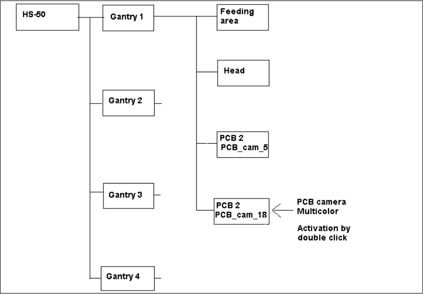
: The "Main view of "Structure editor" is displayed automatically.
As shown afterwards, the selected machine is displayed graphically and with the pertinent sub-
structures (component feeding areas, placement heads, PCB cameras, options, etc.).
Abb. 2.7.1 Structural Overview