00193733-02.pdf - 第74页
2 Assembly Instructions PCB Camera, Multicolor SIPLACE F5 HM SIPLACE F5 HM 2.8 SITEST: Configuration and Illumination Check of all PC B Cameras Multicolor 05/2 007 Edition 74 : Click on the button "Illumination valu…
SIPLACE F5 HM 2 Assembly Instructions PCB Camera, Multicolor SIPLACE F5 HM
05/2007 Edition 2.8 SITEST: Configuration and Illumination Check of all PCB Cameras Multicolor
73
2.10.2 Illumination Check
NOTE:
We recommend that you conduct the illumination check be performed after the PCB camera Mul-
ticolor is assembled, reinstalled or exchanged. By appropriately switching over the vision screen
(see User Manual) it is possible to precisely check the function of the pertinent light level and, for
example, the change from full to one-half brightness. 2
2
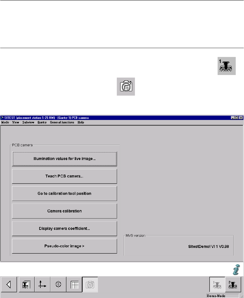
: In the SITEST program 407.xx select the ICON "Gantries" and then the "Gantry 1" .
: Click on the CON "PCB camera functions" .
The following screen is displayed:
Fig. 2.10.2 Menu "Setting of Illumination" for PCB Camera"
2
2
2
2 Assembly Instructions PCB Camera, Multicolor SIPLACE F5 HM SIPLACE F5 HM
2.8 SITEST: Configuration and Illumination Check of all PCB Cameras Multicolor 05/2007 Edition
74
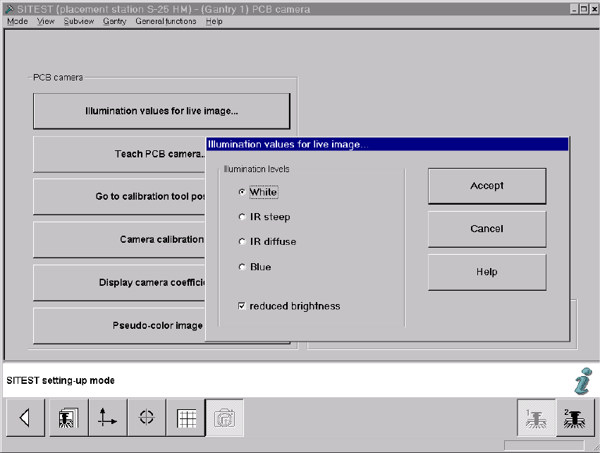
: Click on the button "Illumination values for live image".
In principle, you can use this function to test whether the illumination of the PCB camera Mul-
ticolor is activated. The illumination levels "White" and "Blue" are visible; "IR" is not.
: The screen "Illumination values for live image" is displayed:
Fig. 2.10.3 Screen: "Illumination Values for Live Image"
: If the Multicolor camera(s) was (were) assembled, reinstalled or exchanged, you must test at
least the illumination levels "White" and "Blue" because their light is visible.
: Click on the "Radio button" to select the illumination level "White".
: Deactivate the button "Reduced brightness" and click on the button "Accept".
The complete illumination level is therefore activated at the outset.
: Switch to the menu "Teach PCB camera" -> Click on the button "PCB camera":
Make a visual check (with safety hoods closed):
The camera’s white light must flash.
: Once again, press the button "Illumination values for live image".
2

SIPLACE F5 HM 2 Assembly Instructions PCB Camera, Multicolor SIPLACE F5 HM
05/2007 Edition 2.8 SITEST: Configuration and Illumination Check of all PCB Cameras Multicolor
75
: Now activate the option "Reduce illumination".
This reduces the illumination level by one-half.
: Click on the button "Accept" again.
: Make a visual check (with the safety hoods closed):
The camera’s white light must flash repeatedly but not as brightly as before.
: Execute the above-described check for illumination level "blue" as well.
: Exit the menu "PCB camera".
: In the menu "PCB functions" select the button "PCB camera".
NOTE:
If you would like to check the IR illumination levels too, perform the above-described operation in
a like manner for these levels also and. Place a white sheet of paper under the camera. As a
check, switch over to the vision screen in each case. 2
: Afterward, test to make certain that the camera illumination goes OFF in response to safety
shutoff, as described in Abschn. 2.11.