00193733-02.pdf - 第57页
SIPLACE F5 HM 2 Assembly Instructions PCB Camera, Multicolor SIPLACE F5 HM 05/2007 Edition 2.6 Assembly Term inal pan els and Illumination cable 57 2.6.3 Removing PCB Camera (Normal Illu mination) incl. Ob lique Illumina…
2 Assembly Instructions PCB Camera, Multicolor SIPLACE F5 HM SIPLACE F5 HM
2.6 Assembly Terminal panels and Illumination cable 05/2007 Edition
56
2.6.2 Assembling in the Terminal Panel, LH Side
2.6.2.1 Changing the "Illumination" Cables
The F5 HM has 2 "illumination" cables: 2
– Cable "illumination, gantry 1": Item no. 00244260-xx
– Cable "illumination, gantry 2": Item no. 00244261-xx
These cables must be changed first, as described below.
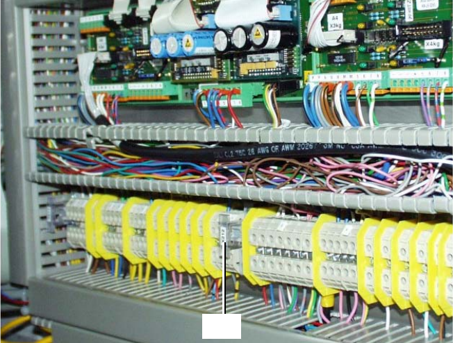
Abb. 2.6.3 Terminal Panel, LH Side, Layout of the Illumination Cables, Gantries 1 and 2
: Open the machine frame doors for terminal panel, LH side.
: Use the circuit diagram Fig. 2.13.6 and change the two cables "illumination, gantry 1" and "2"
as follows:
– Separate the strands wh, gn, gr, bl which are clamped to terminal X212 - 4 with a connector
sleeve.
– Use the crimping pliers. Now clamp these strands separately as follows, each in a twin con-
nector sleeve from the assembly kit (Section 2.4.3):
- wh with gn
- gr with bl
: Clamp the 2 changed "Illumination" cables on the terminal panel:
– the strands wh, gn -> to terminal X212 - 4 (+ 24V),
– the strands gn, bl -> to terminal X212 - 9 (+ 50V)
3
4
X212
SIPLACE F5 HM 2 Assembly Instructions PCB Camera, Multicolor SIPLACE F5 HM
05/2007 Edition 2.6 Assembly Terminal panels and Illumination cable
57
2.6.3 Removing PCB Camera (Normal Illumination) incl. Oblique Illumination
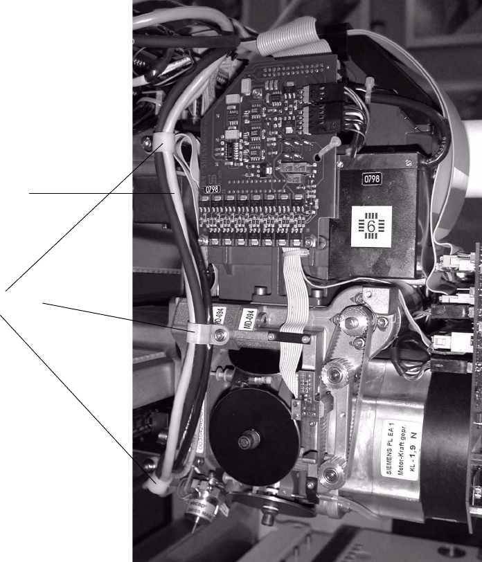
Abb. 2.6.4 Loosening Cable Ties, Removing Subgantry PCB Camera (Using HS-50 as an Example)
: Remove the cover over the placement heads (undo 5 screws on each).
Refer to the note in Abschn. 2.1 regarding the continued use of the covers.
: Cautiously undo the cable ties along the cable harness (Fig. 2.6.10):
: In case of initial situation "old PCB camera with head PCB moduar": On the "Vision board, mo-
dular" unplug the connectors of the subgantry PCB camera (normal illumination) and - if pre-
sent - the oblique illumination (see Fig. 2.13.4 and Fig. 2.13.5).
– Cable, PCB camera (old) -> X4
– Cable, illumination for PCB camera -> X6
– Cable, oblique illumination -> X5
Cable harness
Cable ties
2 Assembly Instructions PCB Camera, Multicolor SIPLACE F5 HM SIPLACE F5 HM
2.6 Assembly Terminal panels and Illumination cable 05/2007 Edition
58
: If the optional oblique illumination (see Abb. 2.6.5) is present on the subgantry PCB camera,
deinstall the oblique illumination as follows:
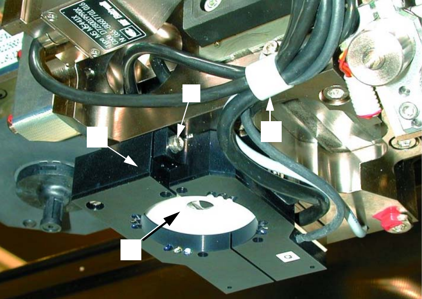
Abb. 2.6.5 Removing the Optional Oblique Illumination
Key: 2
1. Subgantry PCB camera
2. Cable clip: Fastener = 1 socket hex head cap screw M3
3. Optional oblique illumination
4. Fastener for oblique illumination: an attachment screw (socket hex head cap screw M 3)
2
: Undo the cable clip fastener (see Abb. 2.6.5 -> 2).
: Hold onto the oblique illumination:
Undo the attachment screw (socket hex head cap screw M3: see Abb. 2.6.5 -> 2) and pull the
oblique illumination straight down and off the camera.
: Cautiously put the oblique illumination to one side so that it won’t be damaged. The best pro-
cedure is to put it into a suitable package immediately.
: Use a small mirror as an aid and HOLD onto the PCB camera:
Starting from the bottom, undo the screws fastening the PCB camera (3 socket hex head cap
screws M2, see Abb. 2.6.4 -> 4) and lower the PCB camera out.
3
1
2
4