00193733-02.pdf - 第71页
SIPLACE F5 HM 2 Assembly Instructions PCB Camera, Multicolor SIPLACE F5 HM 05/2007 Edition 2.8 SITEST: Configuration and Il lumination Check of all PCB Cameras Multicolor 71 2.8 SITEST : Configuration a nd Illumination C…
2 Assembly Instructions PCB Camera, Multicolor SIPLACE F5 HM SIPLACE F5 HM
2.7 Configuration PCB Camera Multicolor on LC 05/2007 Edition
70
2.7.2 Camera Focus, dependent on PCB/Substrate Thickness
The focus level for the current substrate or PCB thickness can be optimized by installing or remo-
ving the distance plate (spacer) between the Multicolor PCB camera and camera holder. 2
The decision as to whether or not to work with the distance plate can be made during the course
of the assembly on the basis of the table (see Abschn. 2.6.4). As a final check, a specification can
be accessed at the line computer as described below: 2
: After describing the PCB, including entering the PCB/substrate thickness (= height) in the clu-
ster editor, conducting the produceability check and specifying the job for the relevant station
in the job editor you can check under -> Services -> Error messages.
If a change must be made involving the distance plate (spacer), a message such as the follo-
wing one is displayed:
Warning: PCB xxx.la is more than 3.400 mm thick (x.y > 3.400 mm)
For this reason, camera 18 must be mounted without the spacer.
OR
Warning: PCB xxx.la is less than 1.500 mm thick (x.y < 1.500 mm).
For this reason, camera 18 must be mounted with the spacer.
xxx.la = name of PCB
x.y = in the cluster editor entered thickness (height) of the PCB / substrate
Camera 18 = PCB camera Multicolor
: Continue with the activation / configuration and the illumination check (see Abschn. 2.8).
SIPLACE F5 HM 2 Assembly Instructions PCB Camera, Multicolor SIPLACE F5 HM
05/2007 Edition 2.8 SITEST: Configuration and Illumination Check of all PCB Cameras Multicolor
71
2.8 SITEST: Configuration and Illumination Check of
all PCB Cameras Multicolor
DANGER
During the following work, pay attention to the DANGER text regarding work with the SITEST pro-
gram in Abschn. 2.2. 2
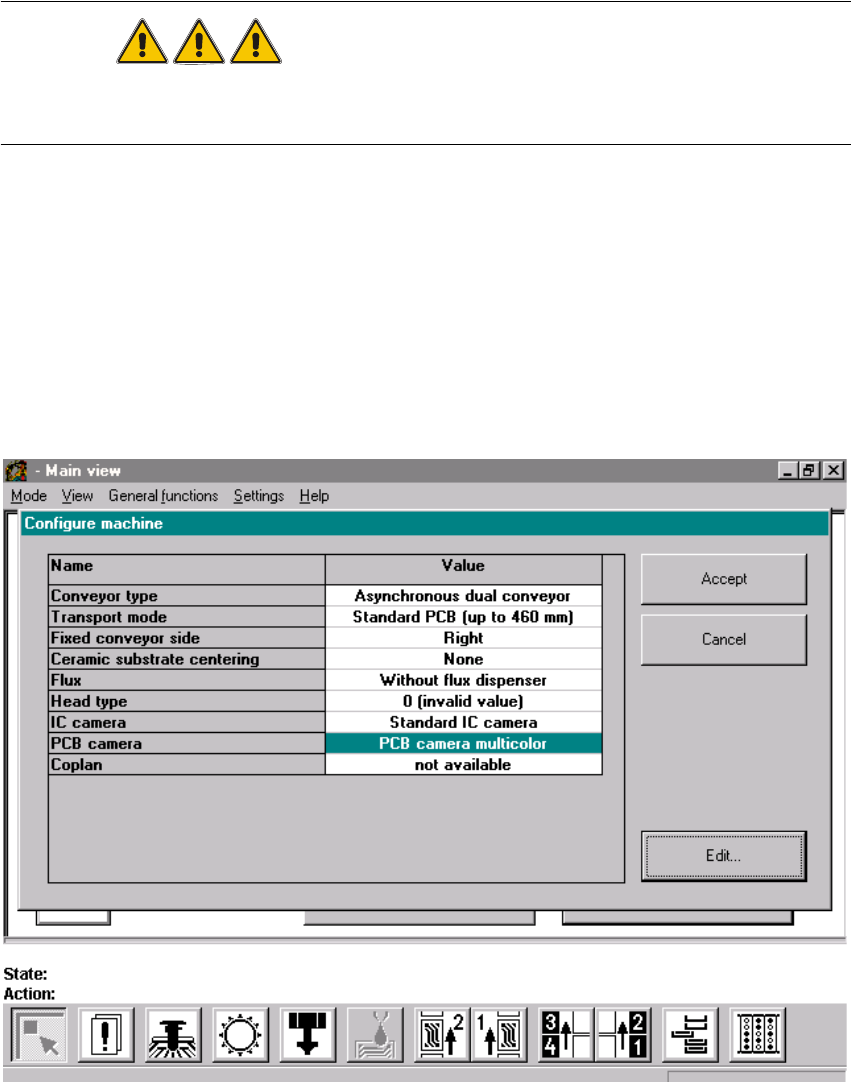
2.10.1 Configuration
: Boot the machine and change over into the SITEST program.
: Select "Settings" -> "Machine configuration".
: Select: "PCB camera" -> "Edit" (button).
: The "Edit" window is displayed:
Fig. 2.10.1 "Edit" Window: Selecting the PCB Camera Multicolor
2 Assembly Instructions PCB Camera, Multicolor SIPLACE F5 HM SIPLACE F5 HM
2.8 SITEST: Configuration and Illumination Check of all PCB Cameras Multicolor 05/2007 Edition
72
: In the configuration menu of the gantry, mark the option "Multicolor" and select "Accept" (but-
ton).
: Conduct the illumination check for the PCB cameras Multicolor as described below in Abschn.
2.10.2.
: Exit the menu "Machine configuration" by pressing "Accept".
: Power down the machine and execute a new start so that the configuration will be accepted.
: Next, return to the SITEST program.
: In the main view, press the button "Total reference run".
: Afterwards, conduct the calibration:
Whenever the PCB camera Multicolor is assembled, reinstalled or exchanged, all of the place-
ment heads and cameras must be calibrated - after the overall reference run - as described in
the User Manual SITEST SW V 407.xx.