00193733-02.pdf - 第53页
SIPLACE F5 HM 2 Assembly Instructions PCB Camera, Multicolor SIPLACE F5 HM 05/2007 Edition 2.6 Assembly Term inal pan els and Illumination cable 53 2.6 Assembly T erminal p anels and Illumination cable 2.6.1 Assembling i…
2 Assembly Instructions PCB Camera, Multicolor SIPLACE F5 HM SIPLACE F5 HM
2.5 Preparatory Steps 05/2007 Edition
52
2.5 Preparatory Steps
: Open the safety hoods and the safety doors on the area of component feeders.
: Push the gantry out of the vicinity of the component changeover table until it is above the PCB
conveyor area.
: Turn the machine off at the main switch, isolate the machine from the mains, turn OFF the flow
of compressed air at the compressed air unit (see DANGER text in Abschn. 2.2).
: Push the X-gantry toward the outside of the machine so that the placement head is readily ac-
cessible.
SIPLACE F5 HM 2 Assembly Instructions PCB Camera, Multicolor SIPLACE F5 HM
05/2007 Edition 2.6 Assembly Terminal panels and Illumination cable
53
2.6 Assembly Terminal panels and Illumination cable
2.6.1 Assembling in the Terminal Panel, Right Side
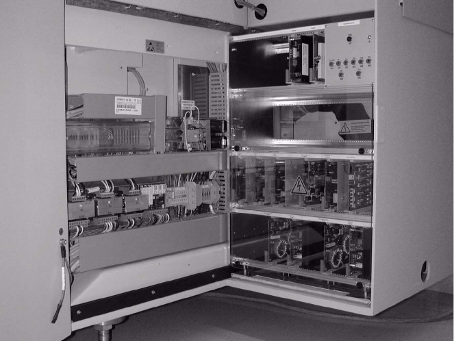
Abb. 2.6.1 Opening the Machine Frame Doors (Service Cabinets for Terminal Panel, Right Side)
Key:
1. Machine frame doors
2. Lateral protection (remains installed)
: Open the machine frame doors on the terminal panel, right side: see Abb. 2.6.1.
: Loosen the screw fastening the servo unit (loosen the M5 socket hex head screw) and lift the
servo unit out.
: Use the following Abb. 2.6.2 and the circuit diagram, Fig. 2.13.6:
2 Assembly Instructions PCB Camera, Multicolor SIPLACE F5 HM SIPLACE F5 HM
2.6 Assembly Terminal panels and Illumination cable 05/2007 Edition
54
2.6.1.1 Installation Steps in the Terminal Panel, Right Side
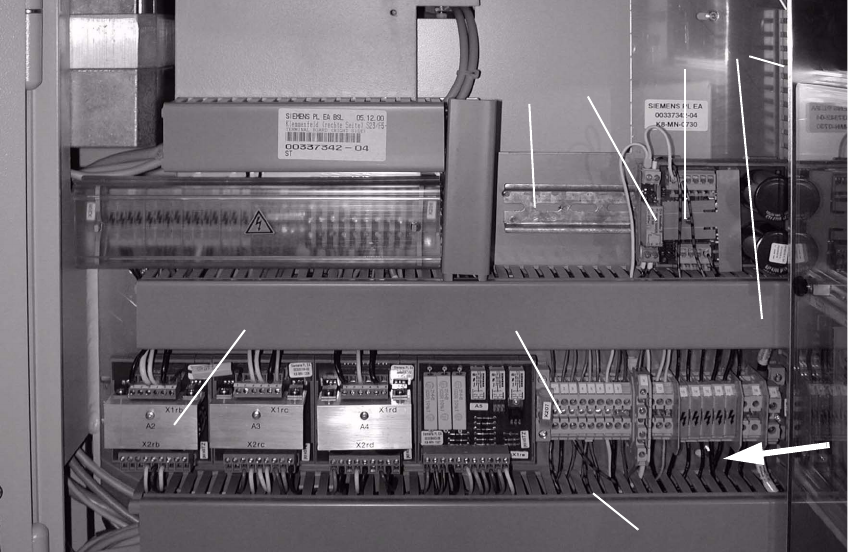
Abb. 2.6.2 Terminal Panel, RH Side: X207; Location for Install. Voltage Module 50 V + Relay K1
Key: 2
1. Servo-unit (remove)
2. Cable pits: remove cover
3. Top hat rail
4. 50 V voltage regulator module 50 F5 HM
5. Relay K1 F5 HM
6. Terminal strip X207
7. Rectifier module A2
2
: Clip the 50 V voltage regulator module (= converter, Item no. 00349095-01, see assembly kit)
onto the top hat rail on the RH side.
: Clip the relay K1 left, onto the top hat rail next to the voltage regulator module.
1
2
4
5
3
6
7
2