CP7 training(6.0) (1).pdf - 第108页
FK-9F98-27 CP-7 Series Traini ng Text for Service Engineers Edition 6.0 Chapter 7. Cam era Adjustment [2 / 16] 4. Remove the lens assembly by unscrewing it from the CCD m odule (figure 3). Figure 3 5. When installing the…
FK-9F98-27 CP-7 Series Training Text for Service Engineers
Edition 6.0 Chapter 7. Camera Adjustment [1/16]
Chapter 7 Camera Adjustment
Parts Cameras
Two CCD cameras are mounted on the machine for inspection of the parts picked at the first station.
The raw image is captured by the cameras and compared with part data to ensure that the part’s
dimensions are within specified tolerances.
Problems that arise from an incorrectly adjusted camera include displaced parts, high error rates, and
skewed parts. Some other examples of possible reasons for re-calibration are:
• Lens replacement
• Camera replacement
Figure 1
7.1 Parts Camera removal
1. With the machine power OFF, remove the video cables from the cameras.
2. Remove the cameras from the machine.
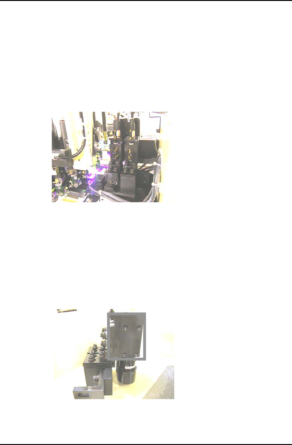
3. Remove the four mounting bolts from the right hand side of the bracket and carefully remove the
cameras. (The four bolts within the rectangle in figure 2). When replacing the camera, the torque
value for tightening these bolts is 0.98N.m. (10Kgf/cm)
Figure 2
Fuji Machine Mfg. Co., Ltd. (Okazaki)
SMT Equipment Quality Assurance Dept.
CS Section
7-1
FK-9F98-27 CP-7 Series Training Text for Service Engineers
Edition 6.0 Chapter 7. Camera Adjustment [2/16]
4. Remove the lens assembly by unscrewing it from the CCD module (figure 3).
Figure 3
5. When installing the lens unit, apply a small amount of Loctite 425 to the threads and use a 3.92Nm
(“C-Type)” torque wrench to secure the lens unit.
7.2 Camera Settings
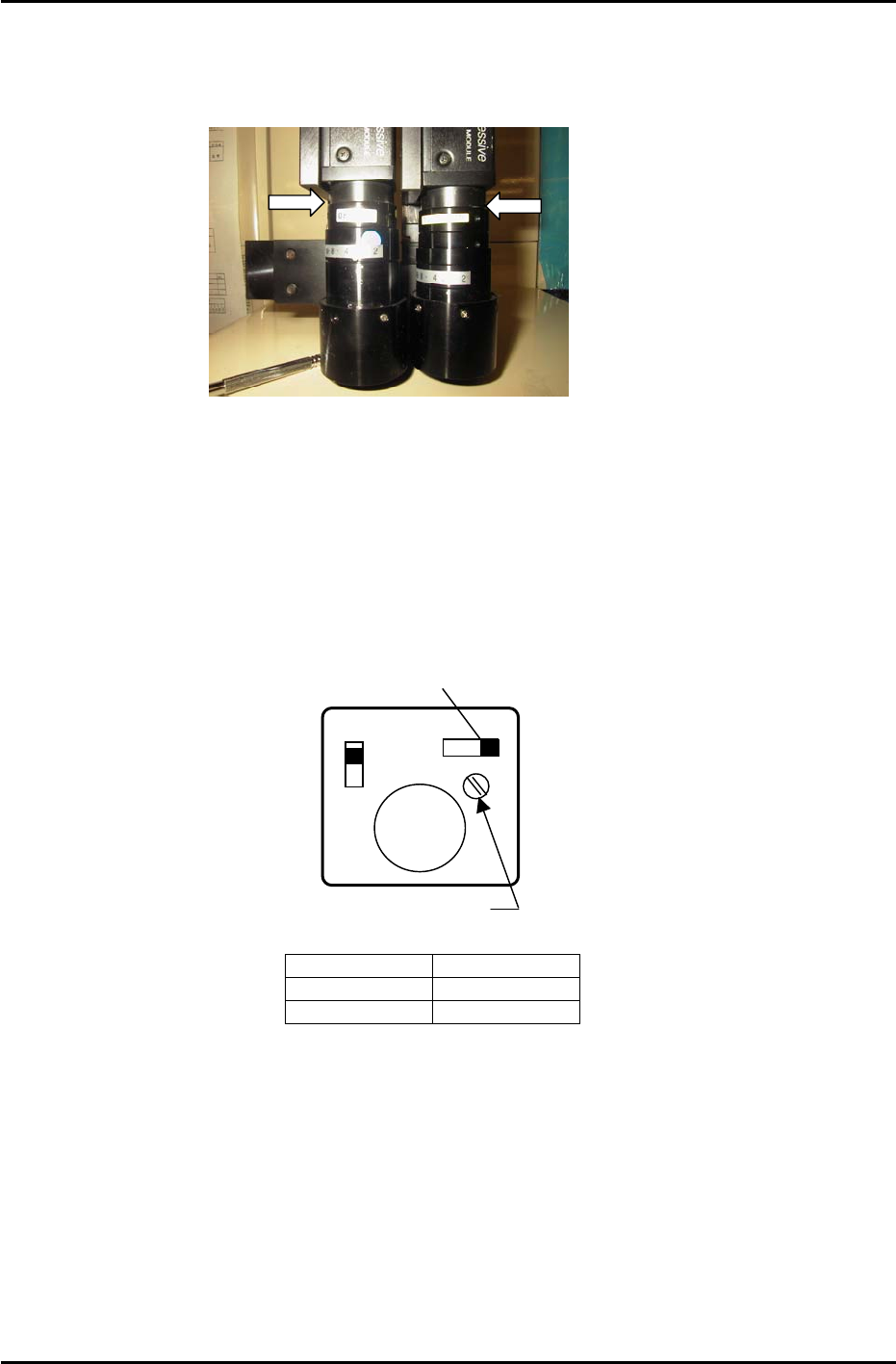
1. Make the following amplifier and aperture settings prior to returning the cameras to the machine:
GAIN switch
Top View
of camera
A
F M
1N
1 l
Manual Gain Adj. Trimmer
GAIN
SIGNAL
Figure 4
Camera Aperture
Wide 2
Narrow 2.8
2. Install the lens assembly to the new CCD module, and then remount the camera and lens unit to the
camera bracket.
3. Install the cameras in the machine.
4. Ensuring that the power supply to the machine is OFF, reconnect the video cables to the cameras.
Fuji Machine Mfg. Co., Ltd. (Okazaki)
SMT Equipment Quality Assurance Dept.
CS Section
7-2
FK-9F98-27 CP-7 Series Training Text for Service Engineers
Edition 6.0 Chapter 7. Camera Adjustment [3/16]
7.3 Camera Set-up Procedure
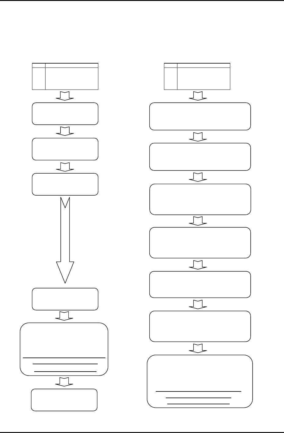
Firmware version V1.18 features a new brightness adjustment function. Use of this function requires a
change in the camera adjustment procedure in order to perform resolution measurements at the
appropriate brightness. Refer to the following diagram for the correct order of adjustment.
V1.17 and prior
V1.18 and later
START
(Mount Camera)
Camera gain adjustment
(Temporary adjustment)
Camera centering
Camera focusing
Camera resolution
measurement
Nozzle check, camera rotation
center &nozzle diameter
measurement
Attach a 0.7 to 2.5 mm nozzle in
all holders and ensure to
perform a nozzle check.
Camera gain
ad
j
ustment
START
(Mount Camera)
Camera gain adjustment
(Temp rarily
in
orary adjustment) Tempo
c
r
e
ase
ga
in if im
age
too
da
rk.
Nozzle check, camera rotation
center &nozzle diameter
measurement
Attach a 1.3 to 2.5 mm nozzles in
all holders and ensure to
p
erform a nozzle check.
Camera focusing
The height of the cameras should
be set to the approximate center of
the in-focus range.
Camera gain adjustment
Ensure to use the V1.18 camera
adjustment method with a 1.3 mm
nozzle in holder 1.
Nozzle brightness check (A1)
Ensure to adjust the brightness level
(A1) prior to the resolution adjustment.
Camera centering
Camera resolution measurement
Fuji Machine Mfg. Co., Ltd. (Okazaki)
SMT Equipment Quality Assurance Dept.
CS Section
7-3