CP7 training(6.0) (1).pdf - 第23页
FK-9F98-27 CP-7 Series T raini ng T ext for Service Engineers Edition 6.0 Chapter 3. X, Y , Z and D-axes Adjustm ent [9/36] 3.5 X/Y T able Squaring Check Check the squaring of the X/Y table using the jig plate. CP-732/73…
FK-9F98-27 CP-7 Series Training Text for Service Engineers
Edition 6.0 Chapter 3. X, Y, Z and D-axes Adjustment [8/36]
CP-732/733E
Y Axis Calibration Data Item
Reference Value (0.002mm/pulse)
– Mechanical stopper – 2500 +/- 100
– OT sensor – 500 +/- 100
Minimum Limit Position Y (– OT + 500) 0 +/- 100
Loading Position YL IN 2500
Loading Position YL OUT 2500
Mark Read Position YC 175000
PCB Check Position Y 160000
Placing Position Y0 190000
Max Limit Position Y (+ OT – 500) 192500 +/- 1000
+ OT sensor 193000 +/- 1000
+ Mechanical stopper 195000 +/-1000
Table 4
15. Check the sensor reaction by I/O.
<I/O Æ Servo Æ IN>
SX011 Y AXIS +OT (Y plus OT)
SX012 Y AXIS –OT (Y minus OT)
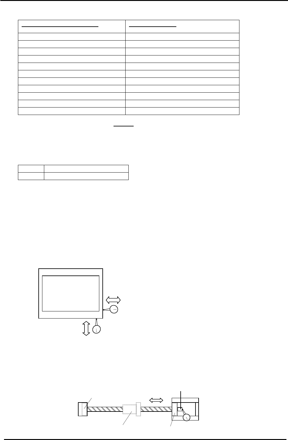
3.4 X and Y Axes Backlash Check
1. Place a (0.002mm) dial gauge against the X-axis of the XY table (Fig.5). Make sure the servo
power is ON, push the XY table left and right by hand to check the amount of backlash.
(Tolerance: 0.010mm.)
2. Check the Y axis in the same manner. Make sure the servo power is ON, push the XY table
back and forth to check the amount of backlash. (Tolerance: 0.010mm.)
XY Table
Backlash check in the X direction
Figure 5
Backlash check in the Y direction
3. If the amount of backlash is out of tolerance, check the following 2 areas.
a. Ball nut
b. Ball screw bearings
Indicate here to check bearings
Bearing
Bearing
Ball Nut
Figure 6
Coupling box
Fuji Machine Mfg. Co., Ltd. (Okazaki)
SMT Equipment Quality Assurance Dept.
CS Section
3-8
FK-9F98-27 CP-7 Series Training Text for Service Engineers
Edition 6.0 Chapter 3. X, Y, Z and D-axes Adjustment [9/36]
3.5 X/Y Table Squaring Check
Check the squaring of the X/Y table using the jig plate.
CP-732/733E (Jig No.: ADCPJ8301)
CP-742/743(M)E (Jig No. ADGPJ8060)
1. Align the jig in the Y direction to zero using a dial gauge.
2. Indicate the jig face in the X direction to check table squaring.
(Tolerance: 0.015 / 239mm)
Squaring Jig
Figure 7
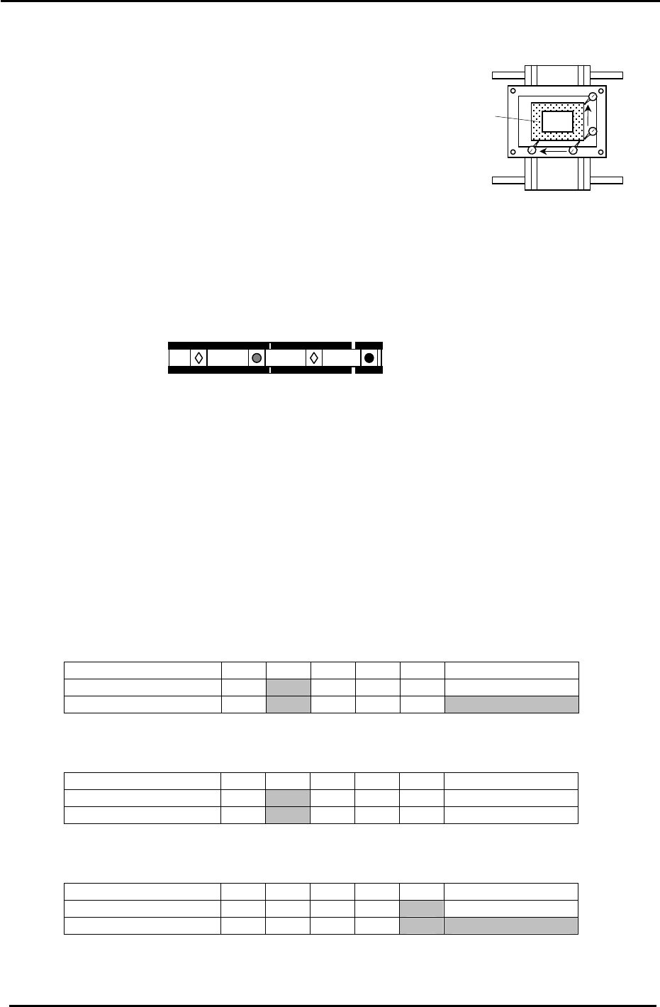
3.6 Reference and Adjustable Pin Alignment Check (CP-742/743(M)E)
Check the alignment and play of the tooling pins as follows.
1. The diagram below shows the tooling pin configuration for the CP-742/743(M)E.
Reference pin B
Reference pin A
Secondary pin B
Secondary pin A
Figure 8
2. To check the alignment of the four pins, place a dial gauge (0.002mm) against reference pin A
and set it to 0.
3. Inch the X/Y table in the X direction and measure the alignment of the three other pins in
relation to reference pin A .
4. Measure at the points indicated in the tables below:
Measuring Point (mm) Max 370 270 170 70 Reference pin A
Center Position 0
Backlash Value
Secondary Pin A:
Center Position Tolerance: +/- 0.050mm. Backlash Tolerance: 0.040mm.
Measuring Point (mm) Max 370 270 170 70 Reference pin A
Center Position 0
Backlash Value
Reference Pin B:
Center Position Tolerance: +/- 0.020mm. Backlash Tolerance: 0.040mm.
Measuring Point (mm) Max 370 270 170 70 Reference pin A
Center Position 0
Backlash Value
Secondary Pin B:
Center Position Tolerance: +/- 0.050mm. Backlash Tolerance: 0.040mm.
(Note: There are no tooling pins on the CP-732/733E.)
Fuji Machine Mfg. Co., Ltd. (Okazaki)
SMT Equipment Quality Assurance Dept.
CS Section
3-9
FK-9F98-27 CP-7 Series Training Text for Service Engineers
Edition 6.0 Chapter 3. X, Y, Z and D-axes Adjustment [10/36]
3.7 X0/Y0 Calibration Data Measurement
X0/Y0 is the placing origin position. Follow the procedure below to carry out the adjustment.
Equipment Checklist:
1- X0/Y0 origin pin jig
1- X0/Y0 special dial gauge set up
1- 3mm L-wrench
1- Small mirror
3.7.1 X0/Y0 Calibration Data Measurement for CP-742/743(M)E
1. Remove the main reference pin and spring then replace the holder.
2. Remove the first claw on the right side of the reference rail.
3. With the cam at 0 degrees, use the I/O to turn the 9th station place solenoid OFF. (Y034)
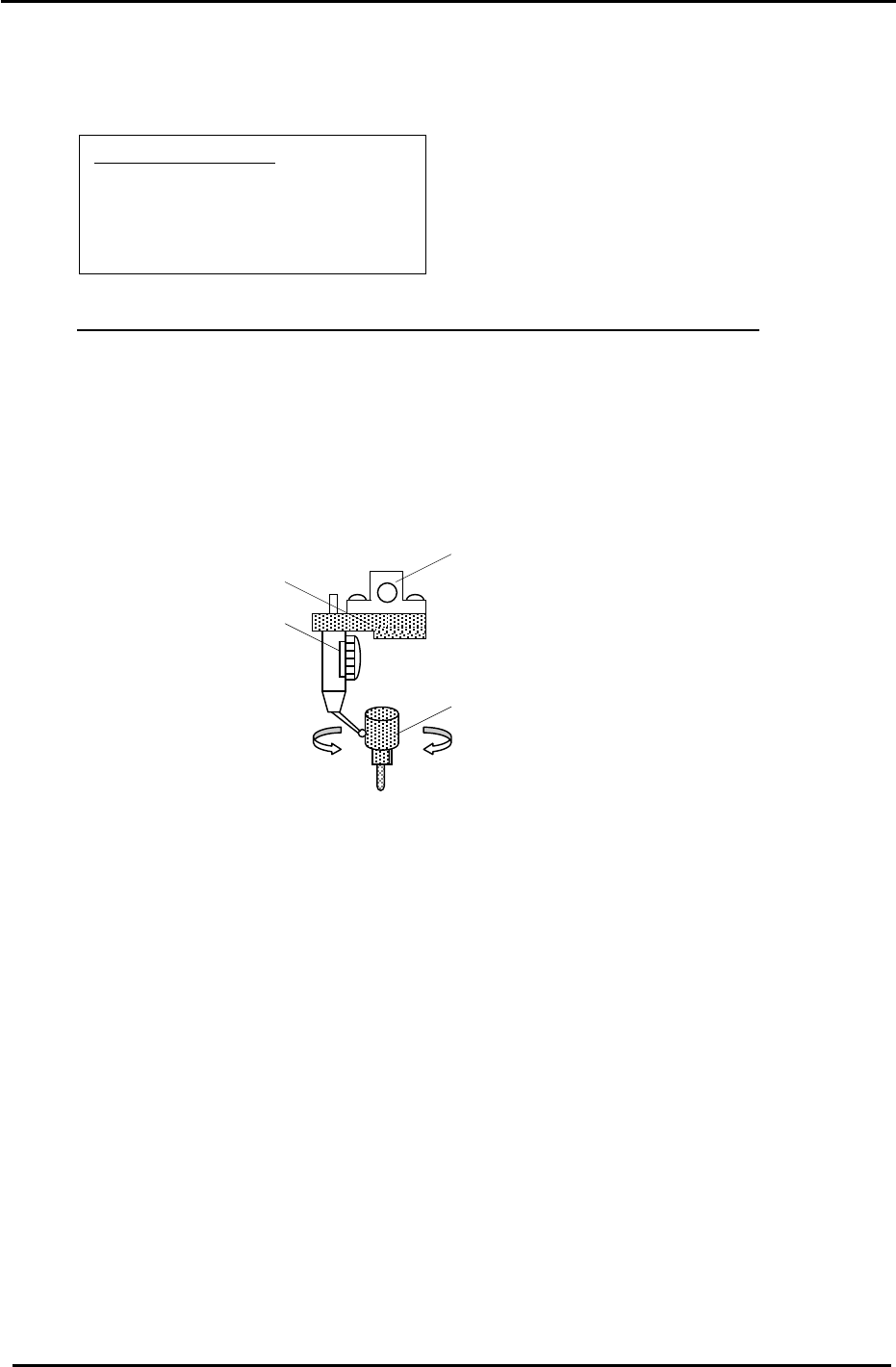
4. Remove holders: A, B & P and attach the X0/Y0 special dial gauge set up on shaft A.
The A Holder
X0/Y0 attachment Jig
Jig Set No.:ADGPJ8010
Dial gauge
Reference Pin Jig
Figure 9
5. Insert the reference pin jig.
6. Measure with the cam angle at 180 degrees.
7. Press the emergency stop button so the machine goes to a servo down condition.
8. Make sure the Z- axis is at the lower limit.
9. Move the XY table manually until the reference pin jig meets the dial gauge on the A holder.
10. Move the table very carefully by hand until you find the point where the dial gauge is zero
throughout the circumference of the reference pin jig. (Tolerance 0+/- 0.01mm)
11. When the position is established, enter it into Calibration Data as follows:
Press: [Maintenance] → [Calibration] → [Placing Reference] → [X0/Y0] → [Set]
12. Finally, remember to remove the dial gauge and jig, but leave the reference pin out until
after the next adjustment: 3.8 XY Table Level Check.
Fuji Machine Mfg. Co., Ltd. (Okazaki)
SMT Equipment Quality Assurance Dept.
CS Section
3-10