CP7 training(6.0) (1).pdf - 第16页
FK-9F98-27 CP-7 Series T raini ng T ext for Service Engineers Edition 6.0 Chapter 3. X, Y , Z and D-axes Adjustm ent [2/36] 12. Set the + OT sensor so that it turns ON 2000 p ulses back from the – mechani cal stopper . I…
FK-9F98-27 CP-7 Series Training Text for Service Engineers
Edition 6.0 Chapter 3. X, Y, Z and D-axes Adjustment [1/36]
CHAPTER 3 X, Y, Z and D-axis Adjustment
3.1 Interference Check
1. Confirm that the X and Y couplings are loosened and check for any interference by moving the
axes through their full movement range manually.
2. Check that the sensors and sensor flags do not collide.
3. Check that the two D-axis pallet up and down cylinders are locked at their lower limit by I/O.
(Y056 D1) (Y067 D2)
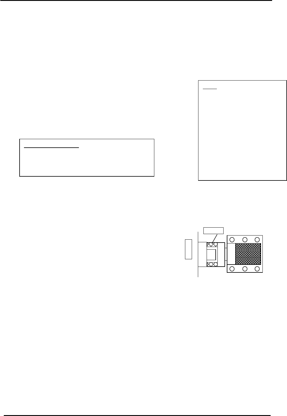
Note:
When the coupling is loose
and the servo ON, vibration
may occur. It is best to lower
the gain level to 1/10 the
original value when carrying
out adjustments. When
completed, remember to
return the gain level to the
original value. Check servo
pack gain parameter: PN100
4. Check that the D-axis stoppers are retracted.
(Y059 D1) (Y069 D2)
3.2 X Axis Adjustment and Calibration Data Setting
Equipment Checklist:
1- 14 N.M torque wrench with 5mm attachment
1- Small size 5mm L-wrench with pipe
1- Small mirror
1- 3mm
T
-wrench
3.2.1 CP-742/743(M)E X-axis Adjustment and Calibration Data Setting
1. Remove the minus OT sensor flag (right side) and check that the coupling is loose.
2. Set the X axis pulse count to 2500.
3. Push the X-axis against the + mechanical stopper.
(right stopper facing machine) Fig.1.
4. Temporarily half lock the coupling with a 5mm wrench and pipe.
X-table
Stopper
Counter Value: 2500 pulses
5. Move the XY table away from the + mechanical stopper.
6. Lock the coupling with a 14N.m torque wrench.
Figure 1
7. Return the XY table to the + mechanical stopper and record the pulse count at this position. It
must be 2500 +/- 100 pulses.
8. Check the alignment of the OT sensor flags and OT sensors.
9. Set the – OT sensor so that it turns ON 2000 pulses back from the + mechanical stopper. It
must be 500 +/- 100 pulses.
10. Move the X-axis back 500 pulses from where the – OT sensor turns ON and set the Calibration
Data value. (Max Limit Position)
Press: [Maintenance] → [Calibration] → [Travel Limits] → [Maximum Limit X]
11. Move the XY table to the – mechanical stopper and record the pulse count at this position. It
must be – 278000 +/- 1000 pulses.
Fuji Machine Mfg. Co., Ltd. (Okazaki)
SMT Equipment Quality Assurance Dept.
CS Section
3-1

FK-9F98-27 CP-7 Series Training Text for Service Engineers
Edition 6.0 Chapter 3. X, Y, Z and D-axes Adjustment [2/36]
12. Set the + OT sensor so that it turns ON 2000 pulses back from the – mechanical stopper. It
must be – 276000 +/- 1000 pulses.
13. Move the X-axis back 500 pulses from where the + OT sensor turns ON and set the Calibration
Data value. (Min Limit Position)
Press: [Maintenance] → [Calibration] → [Travel Limits] → [Minimum Limit X]
14. Table 1 lists the X axis Calibration Data and physical data reference values:
CP-742/743(M)E
X Axis Calibration Data Item Reference Value (0.002mm/pulse)
+ Mechanical stopper 2500 +/- 100
– OT sensor 500 +/- 100
Max Limit Position X (– OT – 500) 0 +/-100
PCB Check Position X (left to right m/c) – 190000
Loading Position XL IN – 271000
Loading Position XL OUT – 11250
Mark Read Position XC (left to right m/c) – 231000
Placing Position X0 (left to right m/c) – 270500
Minimum Limit Position X (+ OT + 500) – 275500 +/- 1000
+ OT sensor – 276000 +/- 1000
– Mechanical stopper – 278000 +/- 1000
Table 1
15. Check sensor reaction by I/O
<I/O Æ Servo Æ IN>
SX009 X AXIS +OT (X Plus OT)
SX00A X AXIS –OT (X Minus OT)
Fuji Machine Mfg. Co., Ltd. (Okazaki)
SMT Equipment Quality Assurance Dept.
CS Section
3-2
FK-9F98-27 CP-7 Series Training Text for Service Engineers
Edition 6.0 Chapter 3. X, Y, Z and D-axes Adjustment [3/36]
3.2.2 CP-732/733E X-axis Adjustment and Calibration Data Setting
Equipment Checklist:
1- 7 N.m torque wrench with 4mm attachment
1- Small size 4mm L-wrench with pipe
1- Small mirror
1- 3mm T-wrench
1- 155mm spacer jig (Jig No.:DCPJ0710)
1. Remove the minus OT sensor flag (right side).
2. Check that the coupling is loose then set the X axis pulse count to – 75000 pulses.
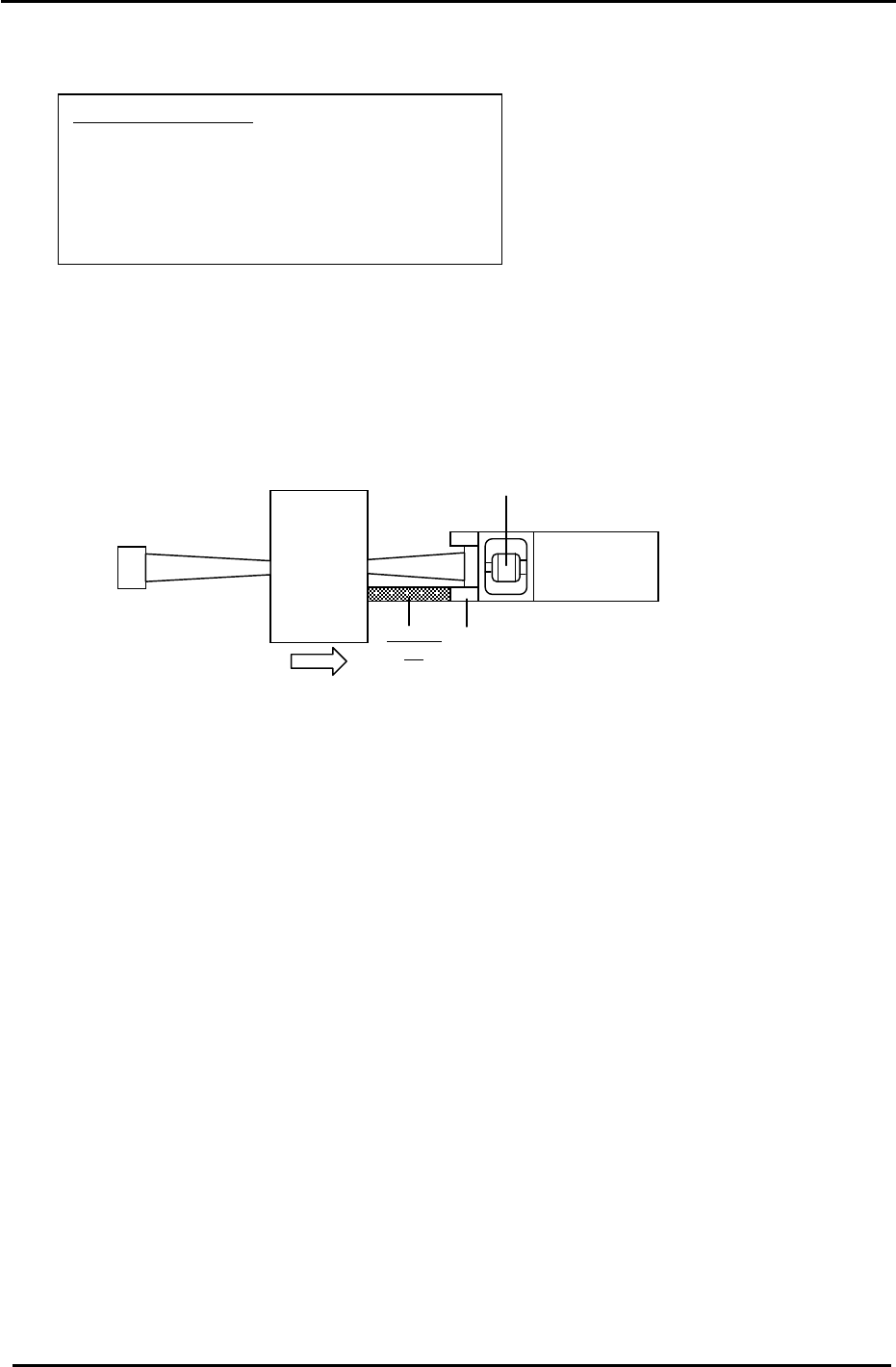
3. Place the 155mm spacing jig (Fig.2) between the X-axis + mechanical stopper and the X-axis
table. Tighten the coupling bolt with a 7N.m torque wrench.
Figure 2
X-Table
X-Motor
Spacing
Jig
Stopper
Coupling
4. Return the XY table to the + mechanical stopper and record the pulse count at this position. It
must be 2500 +/- 100 pulses.
5. Check the alignment of the OT sensor flags and OT sensors.
6. Set the – OT sensor so that it turns ON 2000 pulses back from the + mechanical stopper. It
must be 500 +/- 100 pulses.
7. Move the X-axis back 500 pulses from where the – OT sensor turns ON and set the
Calibration Data value. (Max Limit Position)
Press: [Maintenance] → [Calibration] → [Travel Limits] → [Maximum Limit X]
8. Move the XY table to the – mechanical stopper and record the pulse count at this position. It
must be – 227500 +/- 1000 pulses.
9. Set the + OT sensor so that it turns ON 2000 pulses back from the – mechanical stopper. It
must be – 225500+/- 1000 pulses.
10. Move the X-axis back 500 pulses from where the + OT sensor turns ON and set the
Calibration Data value. (Min Limit Position)
Press: [Maintenance] → [Calibration] → [Travel Limits] → [Minimum Limit X]
Fuji Machine Mfg. Co., Ltd. (Okazaki)
SMT Equipment Quality Assurance Dept.
CS Section
3-3