CP7 training(6.0) (1).pdf - 第131页
FK-9F98-27 CP-7 Series T raini ng T ext for Service Engineers Edition 6.0 Chapter 10. Options [4/6] 3. At 0 degrees, press the [DUS T] button on the amplifi er . If the display indicates “---“, the sensor windows are p r…
FK-9F98-27 CP-7 Series Training Text for Service Engineers
Edition 6.0 Chapter 10. Options [3/6]
10.1.3 Sensor Amplifier Output Voltage Adjustment
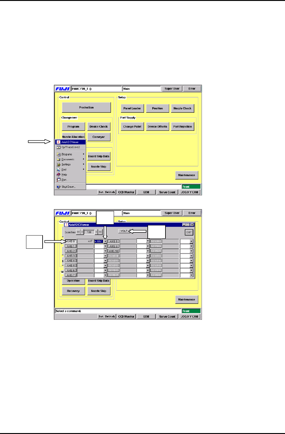
Follow the procedure below in order to set the Nozzle Length Unit amplifier control voltages.
1. Connect the keyboard to the machine. (connect only when the m/c power is OFF)
2. Press the [Windows key] on the keyboard and go to the voltage adjustment display by
selecting, [AxisADCViewer] (Fig 5) Æ [Axis 0] (Fig.6 #1) Æ [select ±10V] (Fig.6 #2) Æ [VOLT]
(Fig.6 #3)
Figure 5
#2
# 1
#3
Figure 6
Fuji Machine Mfg. Co., Ltd. Okazaki
SMT Equipment Quality Assurance Dept.
CS Section
10-3
FK-9F98-27 CP-7 Series Training Text for Service Engineers
Edition 6.0 Chapter 10. Options [4/6]
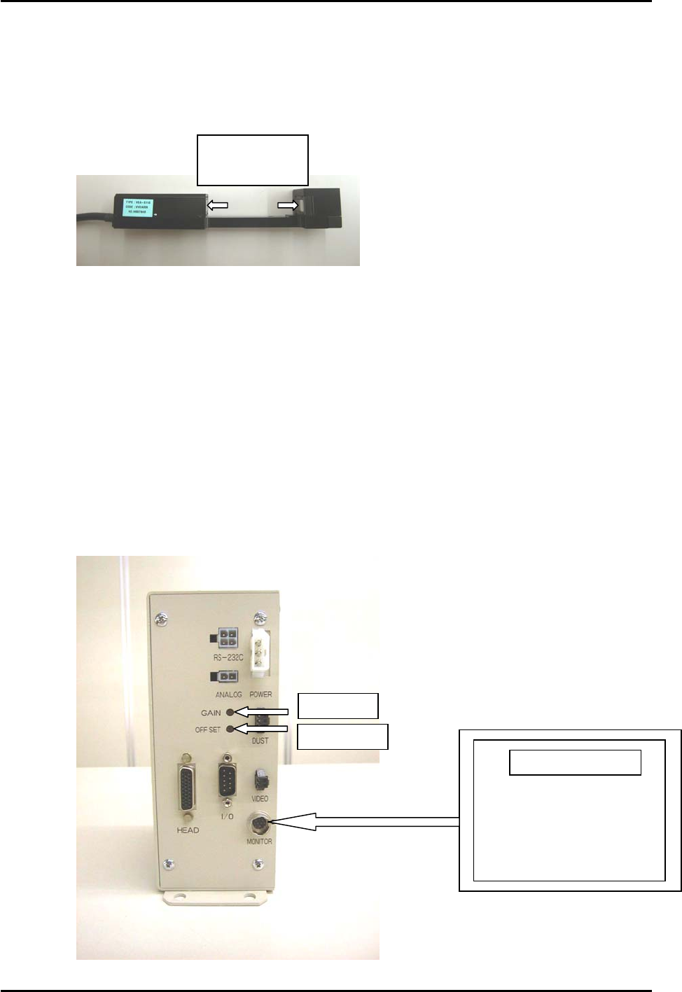
3. At 0 degrees, press the [DUST] button on the amplifier. If the display indicates “---“, the
sensor windows are probably dusty or soiled etc.. Ensure the sensor windows are clean by
wiping them thoroughly with a dry lint free cloth. Press [DUST] again to display the counter.
Clean sensor
windows here
Figure 7
4. Press [INSPECT] to measure.
Check that the amplifier displays “000” (The DUST LED will be ON at this time)
On the main display, the measurement results are displayed “about 1.03V” (“Axis 0”), adjust
the Offset Volume pot on the amplifier so the ”Axis 0” voltage reading is between 0.950 to
1.050V.
5. At a cam angle of 197 degrees, block the sensor completely, then press [INSPECT].
Verify that the amplifier displays “8.00”. If “8.00” does not appear, then the sensor is not
completely blocked.
The measurement results will display at “about 8.97V”. (”Axis 0” voltage reading)
Adjust the Gain Volume on the amp so the ”Axis 0” voltage reading is between 8.950 to
9.050V.
Figure 8
Gain Adj.
OffsetAdj.
Portable Monitor
Fuji Machine Mfg. Co., Ltd. Okazaki
SMT Equipment Quality Assurance Dept.
CS Section
10-4

FK-9F98-27 CP-7 Series Training Text for Service Engineers
Edition 6.0 Chapter 10. Options [5/6]
6. Remove the blockage at the sensor and return the cam angle to 0 degrees.
Press [INSPECT] again to check that the voltage value is less than 1.5V.
7. Press [EXIT].
8. Move Holder A to station 9.5 at 0 degrees and install the nozzle reference jig.
Nozzle Reference Jig
(Jig No.: DCPJ0620)
Figure 9
9. For automatic measuring of the nozzle jig height, Press: [Maintenance] → [Calibration] → [Part
Nozzle Reference ] → [Start].
10. Check that the measurement results are within 1.00 ± 0.3 (0.7 to 1.3)
* Verify that the displayed amplifier value and the measurement results on the display are the
same value.
11. Press: [CLOSE] on the display. A message appears to save proper data, press [YES].
10.1.4 How to avoid problems while adjusting the voltage
1. Do not press the buttons on the unit while the [MODE] LED is flashing (when the raw image is
displayed). Press [MODE], and the LED will turn OFF.
2. The [DUST] LED indicates an abnormal condition. Press [DUST] at cam angle 0 degrees and
the LED will turn OFF.
10.1.5 Amplifier SW and LED functions
[MODE] Switches the monitor output display.
LED ON: Raw Image LED OFF: Memory Image
[INSPECT] Press when issuing measurement commands.
(Measurement should be carried out at 0 degrees)
[DUST] Press this button when registering the black image.(sensor blocked)
(Registered at 0 degrees) The LED will turn ON if an error occurs.
Fuji Machine Mfg. Co., Ltd. Okazaki
SMT Equipment Quality Assurance Dept.
CS Section
10-5