CP7 training(6.0) (1).pdf - 第24页
FK-9F98-27 CP-7 Series T raini ng T ext for Service Engineers Edition 6.0 Chapter 3. X, Y , Z and D-axes Adjustm ent [10/36] 3.7 X0/Y0 Calibration Data Measurement X0/Y0 is the placing origin position. Follow the procedu…
FK-9F98-27 CP-7 Series Training Text for Service Engineers
Edition 6.0 Chapter 3. X, Y, Z and D-axes Adjustment [9/36]
3.5 X/Y Table Squaring Check
Check the squaring of the X/Y table using the jig plate.
CP-732/733E (Jig No.: ADCPJ8301)
CP-742/743(M)E (Jig No. ADGPJ8060)
1. Align the jig in the Y direction to zero using a dial gauge.
2. Indicate the jig face in the X direction to check table squaring.
(Tolerance: 0.015 / 239mm)
Squaring Jig
Figure 7
3.6 Reference and Adjustable Pin Alignment Check (CP-742/743(M)E)
Check the alignment and play of the tooling pins as follows.
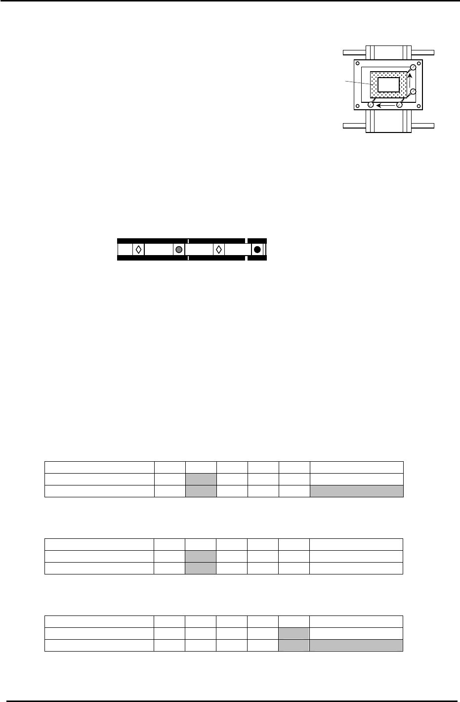
1. The diagram below shows the tooling pin configuration for the CP-742/743(M)E.
Reference pin B
Reference pin A
Secondary pin B
Secondary pin A
Figure 8
2. To check the alignment of the four pins, place a dial gauge (0.002mm) against reference pin A
and set it to 0.
3. Inch the X/Y table in the X direction and measure the alignment of the three other pins in
relation to reference pin A .
4. Measure at the points indicated in the tables below:
Measuring Point (mm) Max 370 270 170 70 Reference pin A
Center Position 0
Backlash Value
Secondary Pin A:
Center Position Tolerance: +/- 0.050mm. Backlash Tolerance: 0.040mm.
Measuring Point (mm) Max 370 270 170 70 Reference pin A
Center Position 0
Backlash Value
Reference Pin B:
Center Position Tolerance: +/- 0.020mm. Backlash Tolerance: 0.040mm.
Measuring Point (mm) Max 370 270 170 70 Reference pin A
Center Position 0
Backlash Value
Secondary Pin B:
Center Position Tolerance: +/- 0.050mm. Backlash Tolerance: 0.040mm.
(Note: There are no tooling pins on the CP-732/733E.)
Fuji Machine Mfg. Co., Ltd. (Okazaki)
SMT Equipment Quality Assurance Dept.
CS Section
3-9
FK-9F98-27 CP-7 Series Training Text for Service Engineers
Edition 6.0 Chapter 3. X, Y, Z and D-axes Adjustment [10/36]
3.7 X0/Y0 Calibration Data Measurement
X0/Y0 is the placing origin position. Follow the procedure below to carry out the adjustment.
Equipment Checklist:
1- X0/Y0 origin pin jig
1- X0/Y0 special dial gauge set up
1- 3mm L-wrench
1- Small mirror
3.7.1 X0/Y0 Calibration Data Measurement for CP-742/743(M)E
1. Remove the main reference pin and spring then replace the holder.
2. Remove the first claw on the right side of the reference rail.
3. With the cam at 0 degrees, use the I/O to turn the 9th station place solenoid OFF. (Y034)
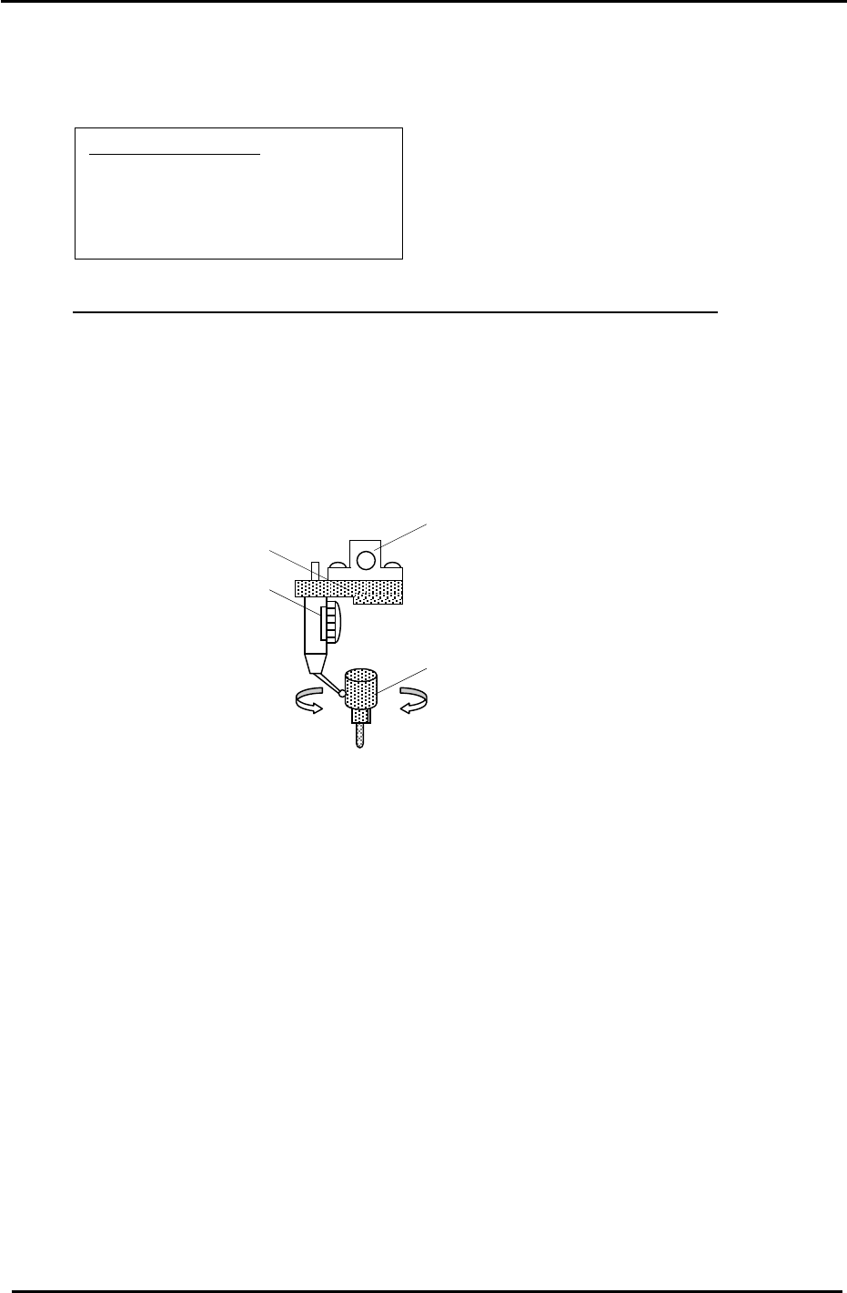
4. Remove holders: A, B & P and attach the X0/Y0 special dial gauge set up on shaft A.
The A Holder
X0/Y0 attachment Jig
Jig Set No.:ADGPJ8010
Dial gauge
Reference Pin Jig
Figure 9
5. Insert the reference pin jig.
6. Measure with the cam angle at 180 degrees.
7. Press the emergency stop button so the machine goes to a servo down condition.
8. Make sure the Z- axis is at the lower limit.
9. Move the XY table manually until the reference pin jig meets the dial gauge on the A holder.
10. Move the table very carefully by hand until you find the point where the dial gauge is zero
throughout the circumference of the reference pin jig. (Tolerance 0+/- 0.01mm)
11. When the position is established, enter it into Calibration Data as follows:
Press: [Maintenance] → [Calibration] → [Placing Reference] → [X0/Y0] → [Set]
12. Finally, remember to remove the dial gauge and jig, but leave the reference pin out until
after the next adjustment: 3.8 XY Table Level Check.
Fuji Machine Mfg. Co., Ltd. (Okazaki)
SMT Equipment Quality Assurance Dept.
CS Section
3-10
FK-9F98-27 CP-7 Series Training Text for Service Engineers
Edition 6.0 Chapter 3. X, Y, Z and D-axes Adjustment [11/36]
3.7.2 X0/Y0 Calibration Data Measurement for CP-732/733E
Equipment Checklist:
1- X0/Y0 origin pin jig
1- X0/Y0 special dial gauge set up
1- 3mm L-wrench
1- Small mirror
1. Remove the first claw on the right side of the reference rail.
2. Install the pin holder jig on the reference rail. Make sure that it is pulled up against the right edge of
the reference rail.
3. With the cam at 0 degrees use the I/O to turn the 9th station place solenoid OFF. (Y034)
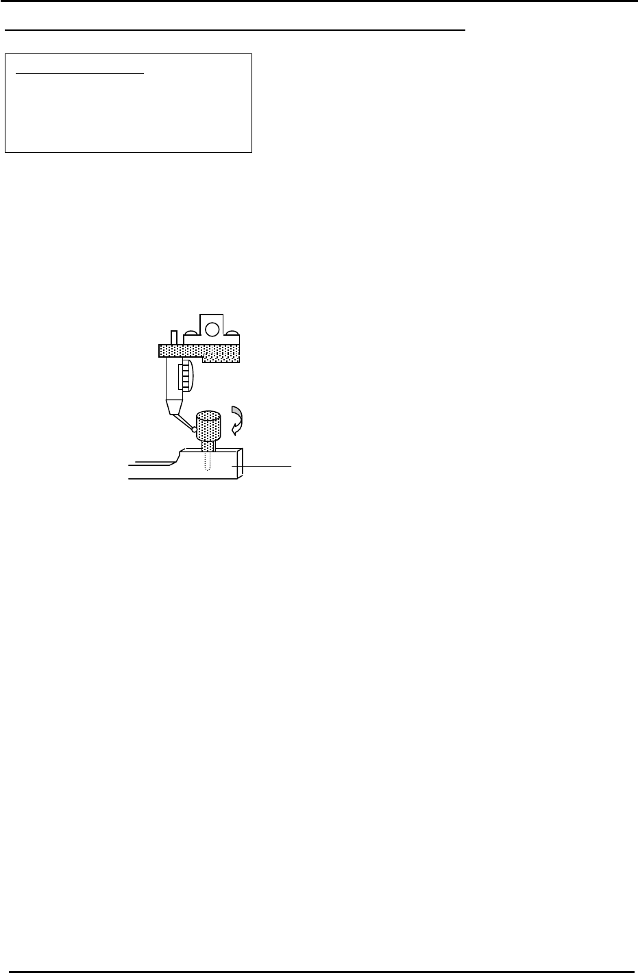
4. Remove holders: A, B & P and attach the X0/Y0 special dial gauge set up on shaft A.
(Jig No.:ADCPJ8080 )
Pin Holder Jig
(Jig No.:ADCPJ8090 )
Figure 10
5. Insert the reference pin jig into the pin holder jig.
6. Measure with the cam angle at 180 degrees.
7. Press the emergency stop button so the machine goes to a servo down condition.
8. Make sure the Z- axis is at its lower limit.
9. Move the XY table manually until the reference pin jig meets the dial gauge on the A holder.
10. Move the table very carefully by hand until you find the point where the dial gauge is zero (or closest
to zero) throughout the circumference of the reference pin jig.
11. When the position is established, enter it into Calibration Data as follows:
Press: [Maintenance] → [Calibration] → [Placing Reference] → [X0/Y0] → [Set]
12. Finally, remember to remove the dial gauge and jig, but leave the reference pin out until after the
next adjustment: 3.8 XY Table Level Check.
Fuji Machine Mfg. Co., Ltd. (Okazaki)
SMT Equipment Quality Assurance Dept.
CS Section
3-11