CP7 training(6.0) (1).pdf - 第11页
FK-9F98-27 CP-7 Series T raini ng T ext for Service Engineers Edition 6.0 Chapter 2. Cam Box Adjustm ent [4/8] 2.7 Helical Gear Backlash Check 1. Check the backlash of the larg e helical gear using a dial indicator with …
FK-9F98-27 CP-7 Series Training Text for Service Engineers
Edition 6.0 Chapter 2. Cam Box Adjustment [3/8]
2.6 Cam-axis Synchronization (Using B-axis Scale)
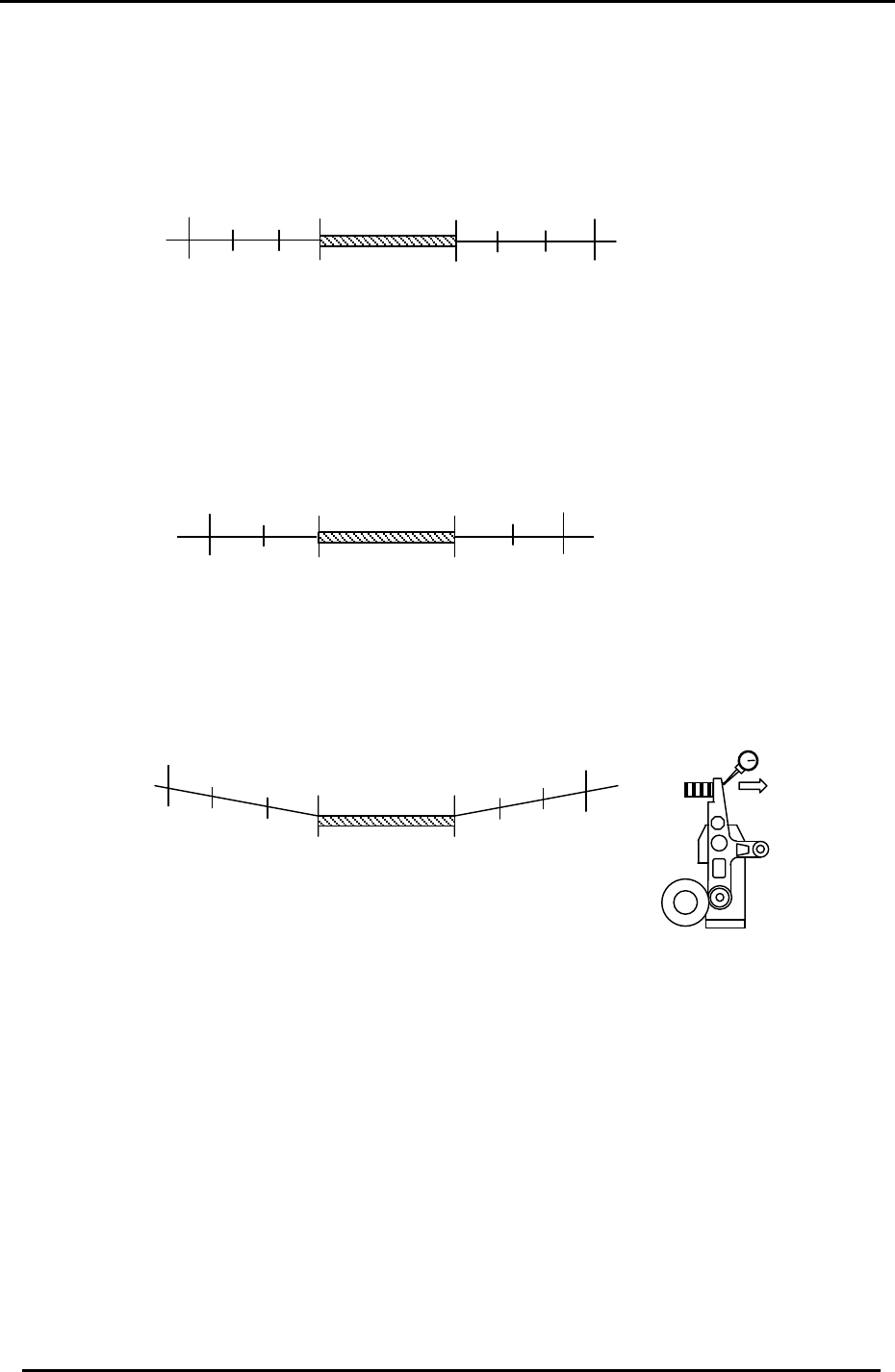
1. Set a dial gauge against the nozzle holder. When the nozzle index stops, the cam angle
should be between 140 and 144 degrees. When starting to move, the cam angle should be
between 234 and 238 degrees.
144
234
Starting point
Stopping point
No movement
range
141
237
(Within 3 degrees on each side)
Figure 4
2. Set a dial indicator on the theta index helical gear. When the theta index stops, the cam
angle should be between 70 and 72 degrees. When starting to move, the cam angle should
be between 296 and 298 degrees.
72
296
Stopping point
298
70
No movement
range
Starting point
(Within 2 degrees on each side)
Figure 5
3. Set a dial indicator on the RQ cam lever (Station 10). Make sure that when the cam lever is
at the low point, the cam axis is between 94 and 274 degrees.
94
274
91
277
No movement
range
(Within 3 degrees on each side)
Stopping point
Starting point
Figure 6
Movement direction
toward low point.
10
th
Sta. Lever
4. After checking the above, ensure the A-axis scale matches the B-axis reference scale.
Notes:
1. In all cases above, the maximum difference between the stopping and starting points
should be within +/- 1 degree.
Example: (fig. 4 above) If the nozzle index stops at 142 degrees, it should begin moving at
236 +/- 1 degree.
2. The exact timing of movement varies a little from machine to machine. (but still within
tolerance). The main point is to ensure that the stopping and starting points are balanced.
Fuji Machine Mfg. Co., Ltd. (Okazaki)
SMT Equipment Quality Assurance Dept.
CS Section
2-3
FK-9F98-27 CP-7 Series Training Text for Service Engineers
Edition 6.0 Chapter 2. Cam Box Adjustment [4/8]
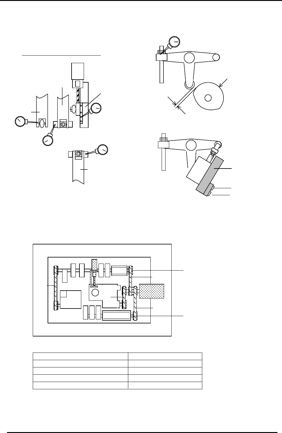
2.7 Helical Gear Backlash Check
1. Check the backlash of the large helical gear using a dial indicator with shafts A, E, I,
and M at station 9. (Cam at 180 degrees)
2. The backlash between the two helical gears should be within 0.02 to 0.06mm.
Figure 7
Theta Index Unit
3. The backlash may be adjusted by moving the theta index unit to the right or left.
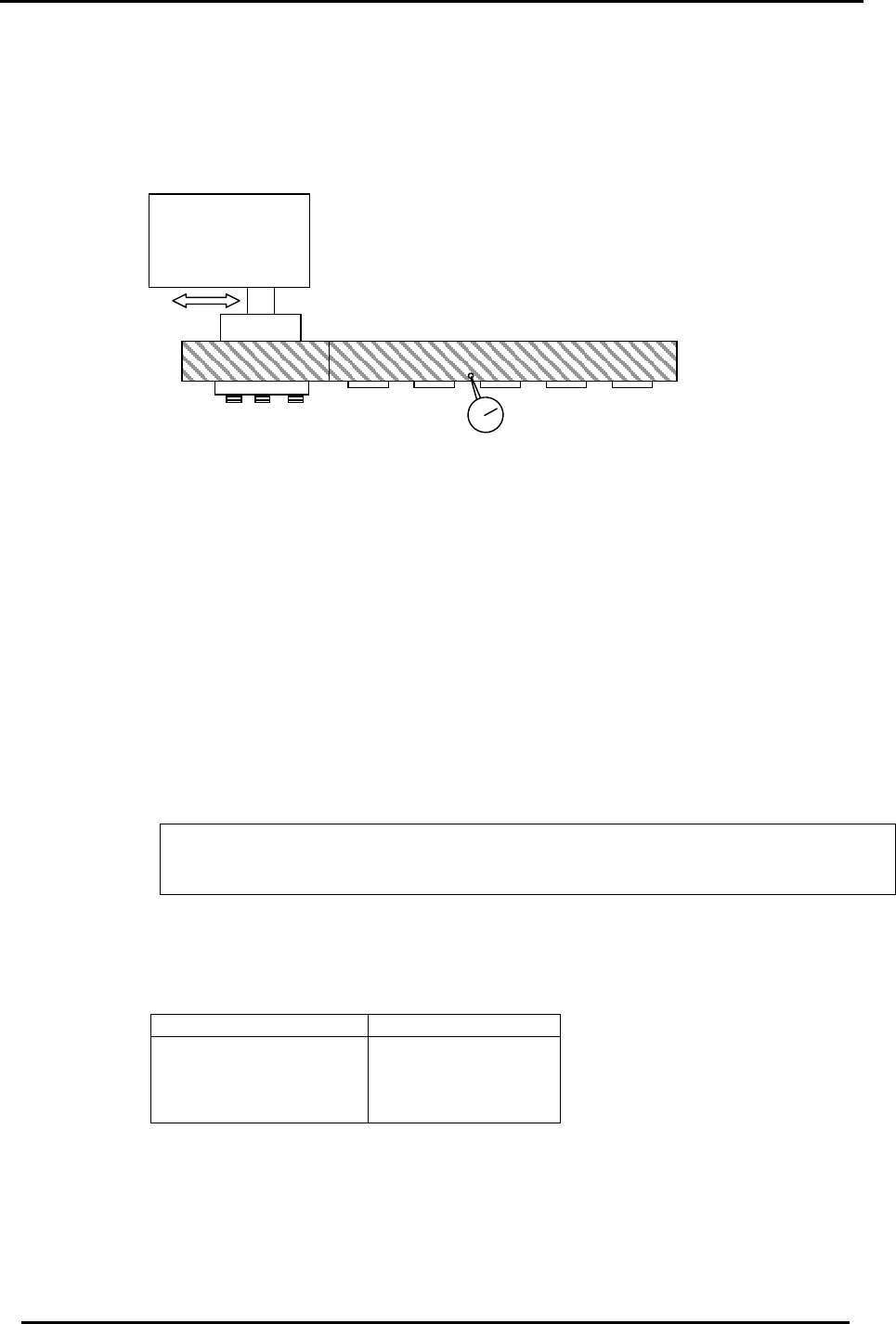
2.8 Cam Lever Stopper Adjustment
1. Turn the machine power OFF.
2. At 0 degrees, set the gap between the cam follower and cam as indicated below for
Station 1 Nozzle up/down, Station 1 tape feed, Station 9 up/down and Station 14
nozzle change.
3. Manually, turn each station’s solenoid valve OFF at zero degrees. (fig. 10)
The solenoid valve should be OFF when setting the dial gauge, and ON when making
adjustments. For the valve buttons: [Green = ON] [Orange = Off]
4. Set a dial gauge on the cam lever at the locations shown in fig 8 and measure the
clearance according to the table below:
Station Appropriate Value
Station 1
Station 9
Station 14
Station 1 Advance
0.04 to 0.06mm
Fuji Machine Mfg. Co., Ltd. (Okazaki)
SMT Equipment Quality Assurance Dept.
CS Section
2-4
FK-9F98-27 CP-7 Series Training Text for Service Engineers
Edition 6.0 Chapter 2. Cam Box Adjustment [5/8]
5. When making adjustments, push the green button (on the valve) to turn the valve ON. Then,
manually toggle the valve ON and OFF to check the clearance. As a rule, set the clearance as
close to 0.04 as possible. (best condition)
CAM
Clearance
Sta. 1
Feeder
advance
Sta. 1
Noz.
Up/Down
Sta. 9
Noz.
Up/Down
Sta. 14
Nozzle
Change
NZ
Dial Gauge Measuring Points
Figure 9
Green = ON
Orange = OFF
Valve
Figure 8
Figure 10
2.9 Cam-axis Timing Belt Tension Adjustment
Timing Belt Tensions in Cam box
4
1
2
3
“B“ Cam
“A “ Cam
Figure 11
Axis Appropriate value (Hz)
1 = Cam Axis A to Cam Motor 129.0 ± 5
2 = Cam Axis B to Cam Motor 99.5 ± 5
3 = Nozzle Index to Cam Motor 227.0 ± 5
4 = Cam Axis B to Theta Index 70.0 ± 5
Fuji Machine Mfg. Co., Ltd. (Okazaki)
SMT Equipment Quality Assurance Dept.
CS Section
2-5