CP7 training(6.0) (1).pdf - 第12页
FK-9F98-27 CP-7 Series T raini ng T ext for Service Engineers Edition 6.0 Chapter 2. Cam Box Adjustm ent [5/8] 5. When making adjustment s, push the green butt on (on the valve) to turn the valve ON. Then, manually toggl…
FK-9F98-27 CP-7 Series Training Text for Service Engineers
Edition 6.0 Chapter 2. Cam Box Adjustment [4/8]
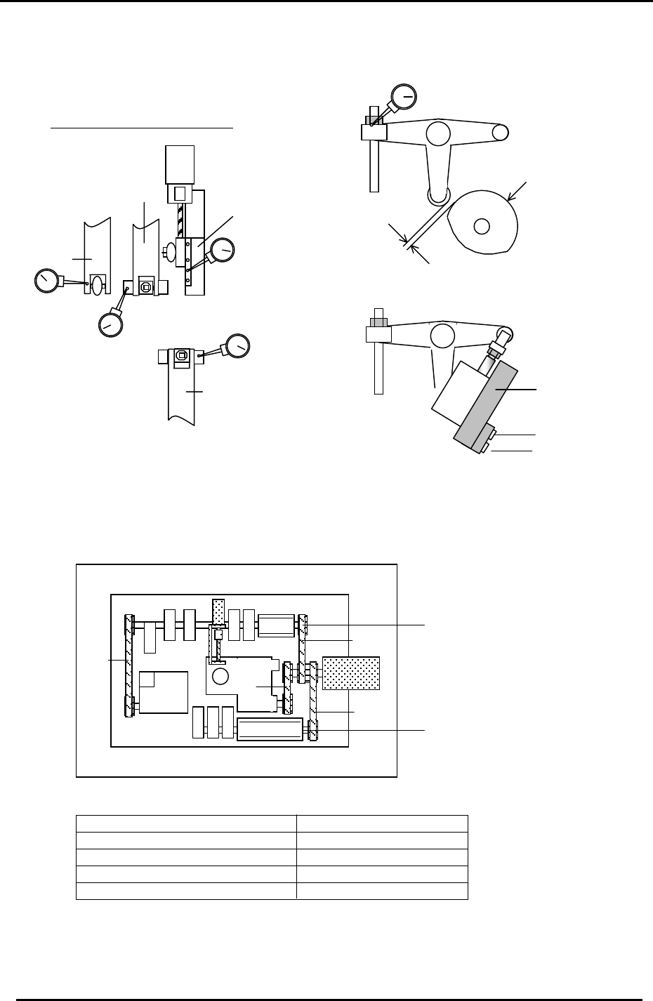
2.7 Helical Gear Backlash Check
1. Check the backlash of the large helical gear using a dial indicator with shafts A, E, I,
and M at station 9. (Cam at 180 degrees)
2. The backlash between the two helical gears should be within 0.02 to 0.06mm.
Figure 7
Theta Index Unit
3. The backlash may be adjusted by moving the theta index unit to the right or left.
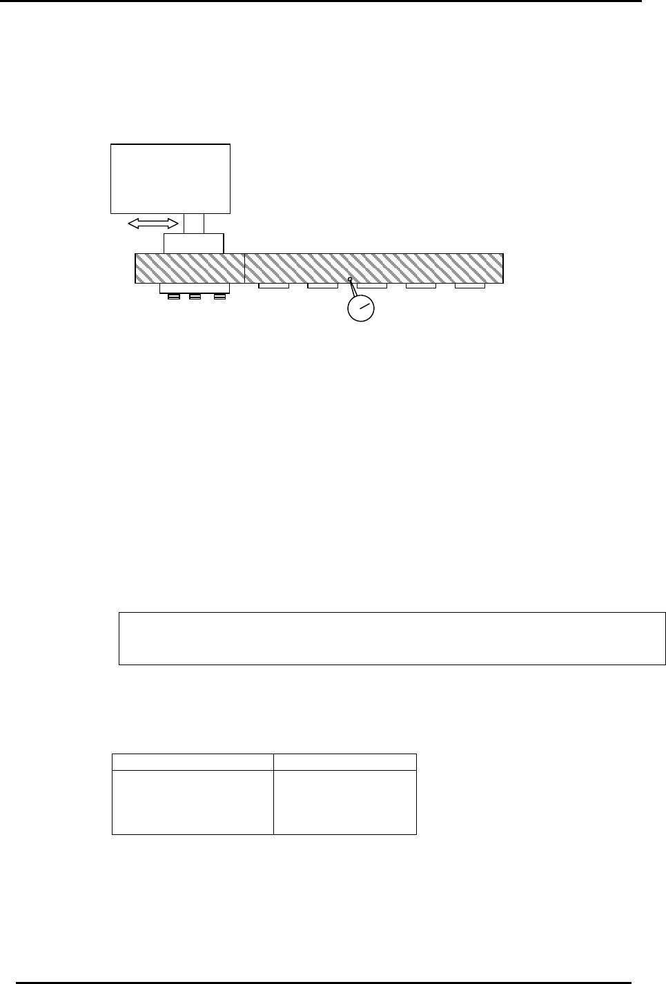
2.8 Cam Lever Stopper Adjustment
1. Turn the machine power OFF.
2. At 0 degrees, set the gap between the cam follower and cam as indicated below for
Station 1 Nozzle up/down, Station 1 tape feed, Station 9 up/down and Station 14
nozzle change.
3. Manually, turn each station’s solenoid valve OFF at zero degrees. (fig. 10)
The solenoid valve should be OFF when setting the dial gauge, and ON when making
adjustments. For the valve buttons: [Green = ON] [Orange = Off]
4. Set a dial gauge on the cam lever at the locations shown in fig 8 and measure the
clearance according to the table below:
Station Appropriate Value
Station 1
Station 9
Station 14
Station 1 Advance
0.04 to 0.06mm
Fuji Machine Mfg. Co., Ltd. (Okazaki)
SMT Equipment Quality Assurance Dept.
CS Section
2-4
FK-9F98-27 CP-7 Series Training Text for Service Engineers
Edition 6.0 Chapter 2. Cam Box Adjustment [5/8]
5. When making adjustments, push the green button (on the valve) to turn the valve ON. Then,
manually toggle the valve ON and OFF to check the clearance. As a rule, set the clearance as
close to 0.04 as possible. (best condition)
CAM
Clearance
Sta. 1
Feeder
advance
Sta. 1
Noz.
Up/Down
Sta. 9
Noz.
Up/Down
Sta. 14
Nozzle
Change
NZ
Dial Gauge Measuring Points
Figure 9
Green = ON
Orange = OFF
Valve
Figure 8
Figure 10
2.9 Cam-axis Timing Belt Tension Adjustment
Timing Belt Tensions in Cam box
4
1
2
3
“B“ Cam
“A “ Cam
Figure 11
Axis Appropriate value (Hz)
1 = Cam Axis A to Cam Motor 129.0 ± 5
2 = Cam Axis B to Cam Motor 99.5 ± 5
3 = Nozzle Index to Cam Motor 227.0 ± 5
4 = Cam Axis B to Theta Index 70.0 ± 5
Fuji Machine Mfg. Co., Ltd. (Okazaki)
SMT Equipment Quality Assurance Dept.
CS Section
2-5
FK-9F98-27 CP-7 Series Training Text for Service Engineers
Edition 6.0 Chapter 2. Cam Box Adjustment [6/8]
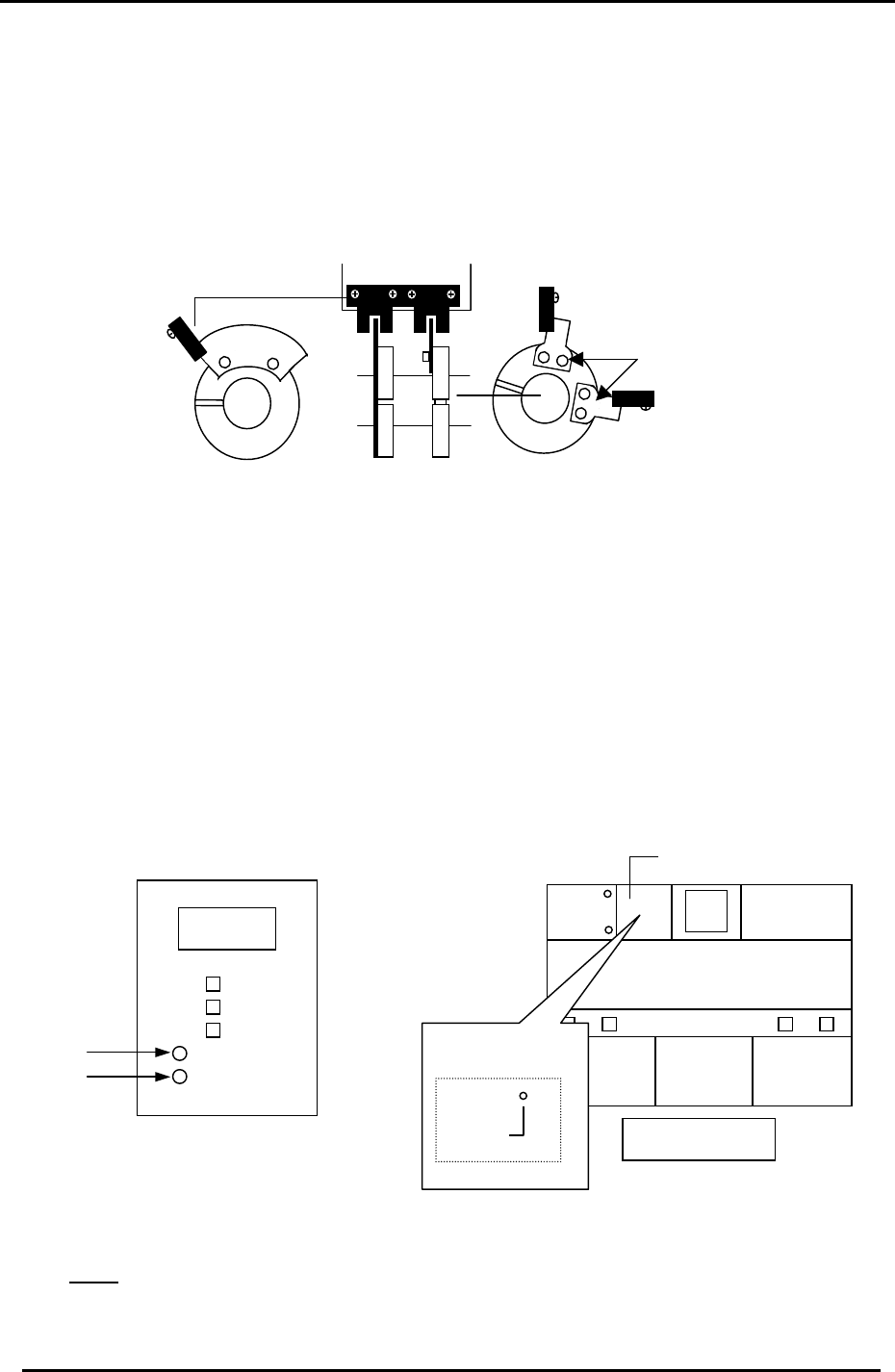
2.10 Image Acquisition Timing Flag Adjustment
1. Adjust the two sensor flags “A” in fig 12, so that the two sensor LED’s turn ON when
rotating the Cam forward to 197 degrees. (Tolerance: 197 ± 1 degree)
2. Adjust flag “B” so the sensor lamp turns ON when rotating the Cam angle forward to 340
degrees. (Tolerance: 340 ± 1 degree). Ensure the LED remains ON for the duration of
time the flag is within the sensor.
Part height trigger sensor * 2
“A”
Dust check trigger sensor *3
“B”
Vision system trigger sensor *1
Figure 12
3. The three sensors mentioned above serve the following purposes.
a. The vision system trigger sensor informs the VP card to take the component image
at 197 degrees. (station 5)
b. The part height trigger sensor informs the part height unit to take the component
thickness (nozzle length) image at 197 degrees. (station 6)
c. The dust check trigger sensor informs the part height unit when to check the
windows for dust etc. (checks from 110 to 340 degrees). (station 6)
Note: The three sensors mentioned above are NOT connected to the I/O. To monitor the
sensor operating conditions, check the LED’s at the following locations:
PCB No.
AEEPE7002
Machine Rear
10LED 1
* 1
1.03
Dust Sensor
Measurement
Sensor
* 3
* 2
Upper left enclosure
Figure 13
Figure 14
Note: In order to monitor the dust sensor signal, go to the I/O and temporarily turn Y042
OFF. Normally, this function is automatically controlled by the system software.
Fuji Machine Mfg. Co., Ltd. (Okazaki)
SMT Equipment Quality Assurance Dept.
CS Section
2-6