CP7 training(6.0) (1).pdf - 第130页
FK-9F98-27 CP-7 Series T raini ng T ext for Service Engineers Edition 6.0 Chapter 10. Options [3/6] 10.1.3 Sensor Am plifier Output V oltage Adjustment Follow the procedure belo w in order to set the Nozzle Length Unit a…
FK-9F98-27 CP-7 Series Training Text for Service Engineers
Edition 6.0 Chapter 10. Options [2/6]
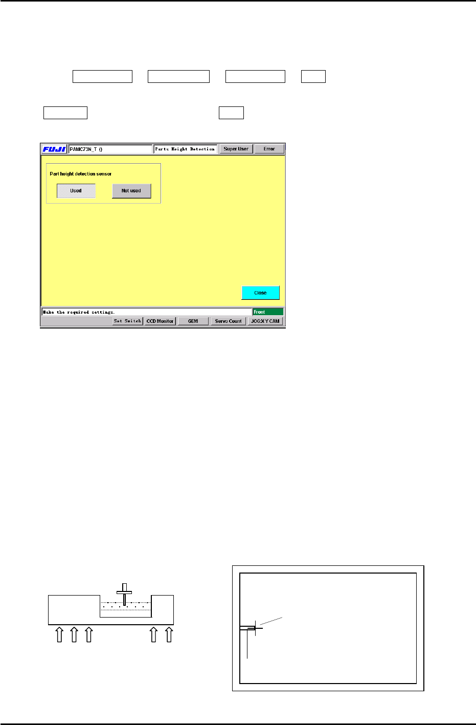
10.1.1 Machine Setting
To enable the “Parts Height” check function, enter the following commands:
Press: Maintenance Æ Configuration Æ Parts Height Æ Used
Note: When re- installing the system software, the default setting is automatically set to
Not Used. Therefore, be sure to set to Used after installing the system software.
Figure 2
10.1.2 Sensor Head Alignment
Follow the procedure below in order to align the nozzle and sensor head appropriately.
1. Connect a portable TV monitor to the output jack on the right side of the controller unit.
2. Place the ”A” shaft at the 6
th
station [parts thickness confirmation sensor] with a 0.7mm
nozzle and set the cam angle to 197 degrees.
3. To display the nozzle image on the monitor, press: [MODE](LED ON) on the sensor amplifier.
Loosen the 5 mounting bolts (Fig.3) for the sensor head (under the cutter plate) and adjust so
the nozzle appears at the left side center of the monitor. (Fig.4)
4. Tighten the mounting bolts using a 3.9Nm torque wrench.
5. Press [MODE] once more Æ [INSPECT], the crosshairs will appear on the display, check
the nozzle center position. Repeat step 3 if the nozzle image is not centered properly.
Nozzle Image
Portable Monitor
Crosshairs
Sensor Head
5 x 3mm Mounting Bolts
Figure 3
Figure 4
Fuji Machine Mfg. Co., Ltd. Okazaki
SMT Equipment Quality Assurance Dept.
CS Section
10-2
FK-9F98-27 CP-7 Series Training Text for Service Engineers
Edition 6.0 Chapter 10. Options [3/6]
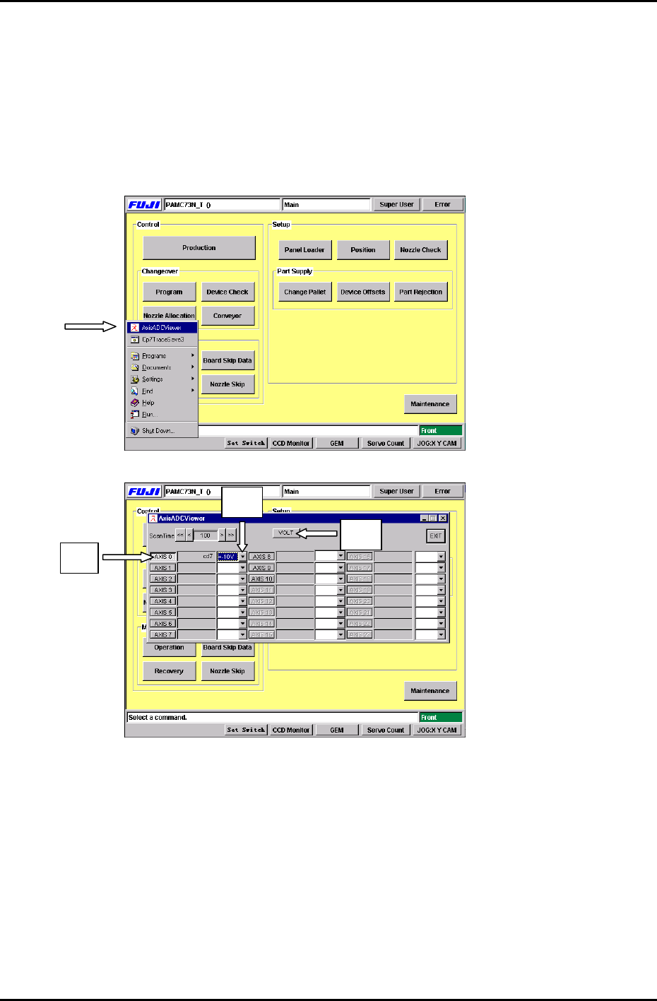
10.1.3 Sensor Amplifier Output Voltage Adjustment
Follow the procedure below in order to set the Nozzle Length Unit amplifier control voltages.
1. Connect the keyboard to the machine. (connect only when the m/c power is OFF)
2. Press the [Windows key] on the keyboard and go to the voltage adjustment display by
selecting, [AxisADCViewer] (Fig 5) Æ [Axis 0] (Fig.6 #1) Æ [select ±10V] (Fig.6 #2) Æ [VOLT]
(Fig.6 #3)
Figure 5
#2
# 1
#3
Figure 6
Fuji Machine Mfg. Co., Ltd. Okazaki
SMT Equipment Quality Assurance Dept.
CS Section
10-3
FK-9F98-27 CP-7 Series Training Text for Service Engineers
Edition 6.0 Chapter 10. Options [4/6]
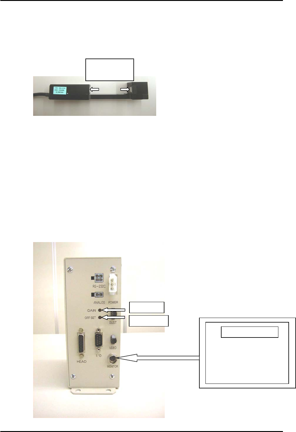
3. At 0 degrees, press the [DUST] button on the amplifier. If the display indicates “---“, the
sensor windows are probably dusty or soiled etc.. Ensure the sensor windows are clean by
wiping them thoroughly with a dry lint free cloth. Press [DUST] again to display the counter.
Clean sensor
windows here
Figure 7
4. Press [INSPECT] to measure.
Check that the amplifier displays “000” (The DUST LED will be ON at this time)
On the main display, the measurement results are displayed “about 1.03V” (“Axis 0”), adjust
the Offset Volume pot on the amplifier so the ”Axis 0” voltage reading is between 0.950 to
1.050V.
5. At a cam angle of 197 degrees, block the sensor completely, then press [INSPECT].
Verify that the amplifier displays “8.00”. If “8.00” does not appear, then the sensor is not
completely blocked.
The measurement results will display at “about 8.97V”. (”Axis 0” voltage reading)
Adjust the Gain Volume on the amp so the ”Axis 0” voltage reading is between 8.950 to
9.050V.
Figure 8
Gain Adj.
OffsetAdj.
Portable Monitor
Fuji Machine Mfg. Co., Ltd. Okazaki
SMT Equipment Quality Assurance Dept.
CS Section
10-4