00196622-03_OM_WPC5_6_EN.pdf - 第30页
Setting up and Commissioning Setting Up the Module 4.2.1 Fitting the Downholde r 30 Operating Manual SIPLACE WPC5/WPC6 4.2 4 . 2 S e t t in g U p t h e M o d u le Setting Up the Module 4.2.1 4 . 2 . 1 F it t in g t h e D…
Setting up and Commissioning
4.1.1 Transport Packaging Delivery Configuration and Transportation
Operating Manual SIPLACE WPC5/WPC6 29
4
4 Setting up and Commissioning
Setting up and Commissioning
4.1
4.1 Delivery Configuration and Transportation
Delivery Configuration and Transportation
4.1.1
4.1.1 Transport Packaging
Transport Packaging
Within Europe the module is transported on a wooden pallet and is wrapped in plastic foil. Outside Eu-
rope, the module is supplied in a wooden crate mounted on a stable wooden pallet.
4.1.1.1
4.1.1.1 Dimensions of the Transport Packaging
Dimensions of the Transport Packaging
4.1.1.2
4.1.1.2 Weight of Module When Ready for Delivery
Weight of Module When Ready for Delivery
The following table contains the weight of the module when ready for delivery.
4.1.2
4.1.2 Delivery Configuration
Delivery Configuration
The WPC5/WPC6 is delivery fully assembled. The upgrade kit is packaged separately.
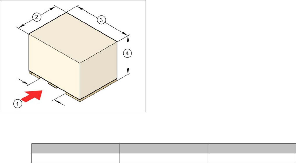
Legende
1. Fork-lift attachment point
2. Width: 1250 mm
3. Length: 1600 mm
4. Height: 1600 mm
Module Dispatch within Europe Dispatch overseas
WPC5/WPC6 400 kg 450 kg
Setting up and Commissioning
Setting Up the Module 4.2.1 Fitting the Downholder
30 Operating Manual SIPLACE WPC5/WPC6
4.2
4.2 Setting Up the Module
Setting Up the Module
4.2.1
4.2.1 Fitting the Downholder
Fitting the Downholder
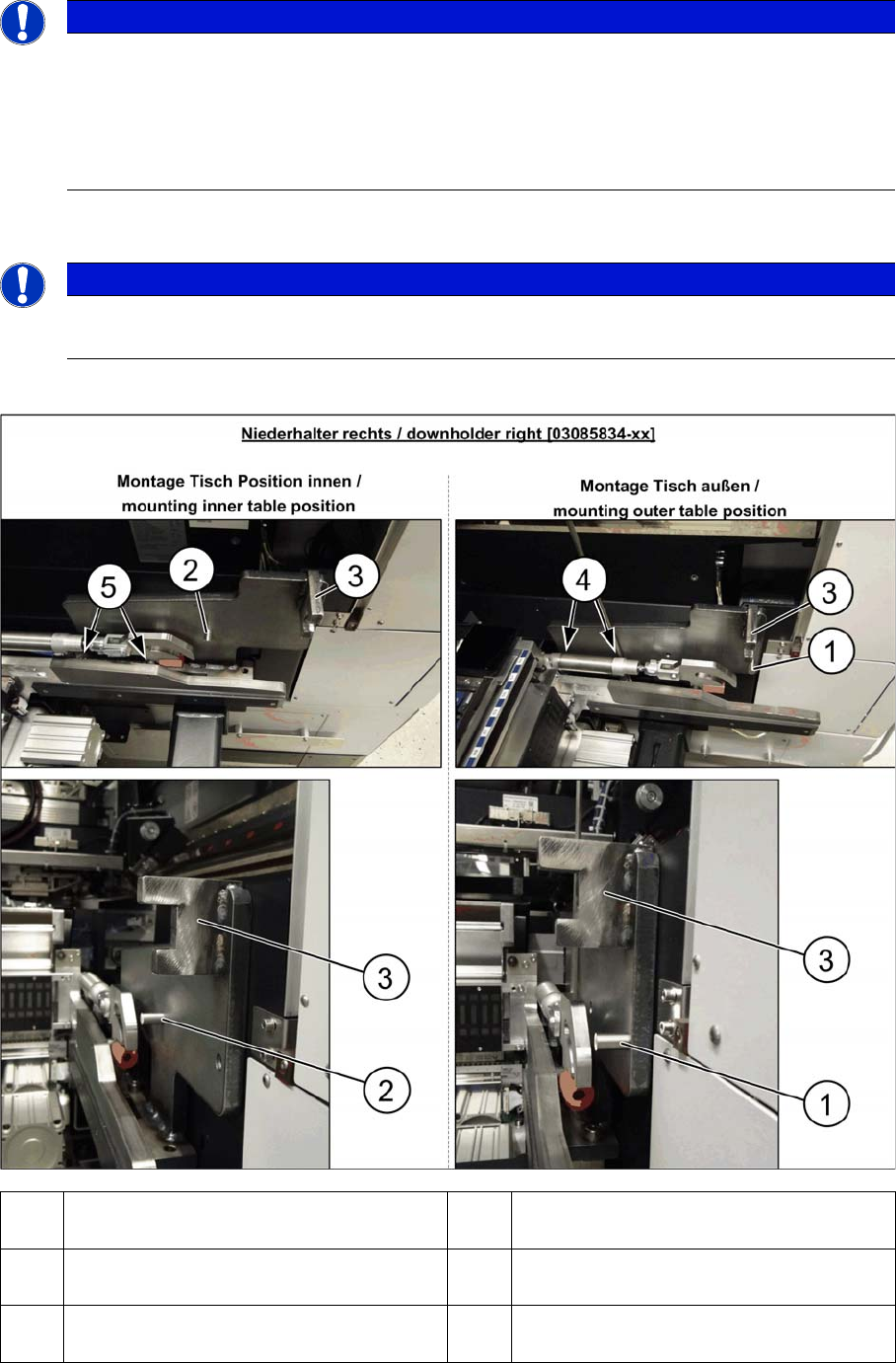
Fitting the right downholder
NOTICE
Requirements
The changeover table insert 30 has to be installed on the respective location.
The WPC5/WPC6 can be used in the SIPLACE SX1/SX2 (depends on head configuration):
► WPC5/WPC6 in SIPLACE SX2 on location 1 und 2.
► WPC5/WPC6 in SIPLACE SX1 only on location 1.
NOTICE
COT-I30 insert for the WPC
When using a COT-I30 insert for the WPC, you only need to fit the downholder on the right.
1 Pin DIN6325-10-M6x30-St [00358814-xx]
at position inside
2 Pin DIN6325-10-M6x30-St [00358814-xx]
at position outside
3 Docking aid 4 Screw ISO4762-M8x40-A2-70 [03042589-
xx]
5 Screw ISO4762-M8x40-A2-70 [03042589-
xx]
Setting up and Commissioning
4.2.1 Fitting the Downholder Setting Up the Module
Operating Manual SIPLACE WPC5/WPC6 31
► Loosen the two screws (4) and (5) on the right side of the COT insert. The screws are underneath
the COT insert cylinder.
► Place the "downholder COT-i right assembly" [03085834-xx] on the right side of the COT insert so
that the holes are aligned with one another.
► Screw the downholder tight with the two new screws (4) and (5).
► The downholder pin (2) must always be approx. 10 mm before the claws of the insert and the dock-
ing aid (3), behind the machine protection (cover flap).
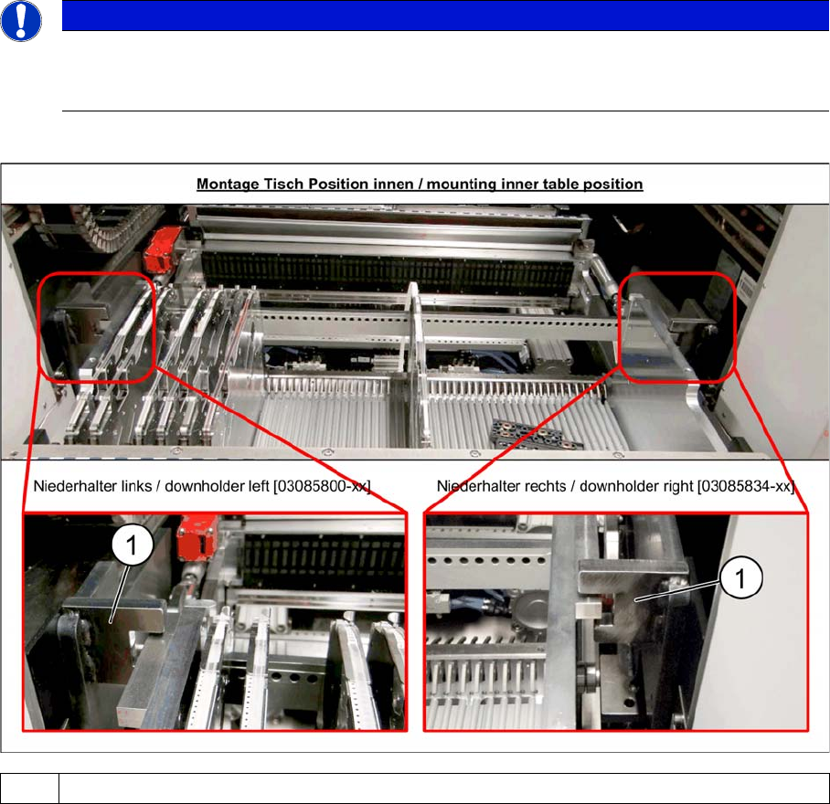
Checking the downholder positions
► Move the component trolley back into the machine.
► The component trolley height must be adjusted so that the side rails fit into the recess on the docking
aid (1). (See also Setting the Changeover Table Height)
NOTICE
Screws
Insert the new screws into the holes in the downholder and position the downholder together
with the screws onto the COT insert.
1Docking aid