00196622-03_OM_WPC5_6_EN.pdf - 第33页
Setting up and Commissioning 4.2.2 Docking the WPC5/WPC6 Setting Up the Module Operating Manual SIPLACE WPC5/WPC 6 33 Aligning the WPC5/WPC6 1. Circular spirit level ► Check the position of the WPC5/WPC6 with the help of…
Setting up and Commissioning
Setting Up the Module 4.2.2 Docking the WPC5/WPC6
32 Operating Manual SIPLACE WPC5/WPC6
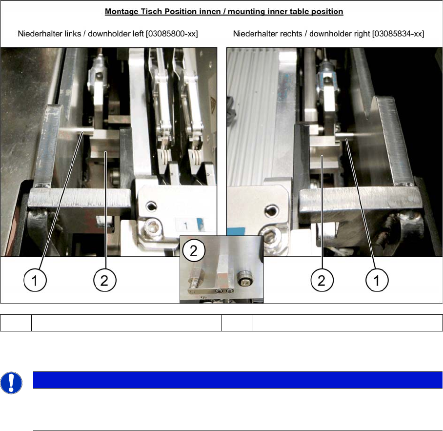
► After pulling the table in through the cylinder, the downholder pin (1) should be up, against the com-
ponent trolley downholder (2).
For removal, follow the instructions in reverse order.
4.2.2
4.2.2 Docking the WPC5/WPC6
Docking the WPC5/WPC6
When installing and removing the WPC5/WPC6, make sure that the arms of the feed axis do not hit any
parts (e.g. stationary cameras etc.).
► If the WPC5/WPC6 is not yet standing on its wheels, fasten the hexagonal shaft (crank handle) to
the lifting mechanism and turn in a clockwise direction, to lift the WPC5/WPC6.
► Stop turning when you have enough room to dock the WPC5/WPC6 onto the machine.
► Open the machine cover on the relevant location.
► If there is a height limiter present in the WPC5/WPC6 location, this needs to be turned over and fixed
into place upside down. Make sure that the height limiter does not touch the cover plate. To do this,
loosen the three screws fastening the height limiter and fit it into the same place upside down (with
two fastening screws).
► Move the WPC5/WPC6 into the location and connect the energy and data supply cable. Make sure
that the arms of the feed axis do not collide with any machine parts.
► Lower the WPC5/WPC6 until it is standing on its feet. Turn the crank handle on the lifting mechanism
until the wheels are about 1 cm above the ground.
1 Downholder pin on the docking aid 2 Component trolley downholder
NOTICE
Wear
In the event of frequent component trolley cycle changes, these parts may become worn. Both
the downholder pin and the component trolley downholder are available as spare parts.
Setting up and Commissioning
4.2.2 Docking the WPC5/WPC6 Setting Up the Module
Operating Manual SIPLACE WPC5/WPC6 33
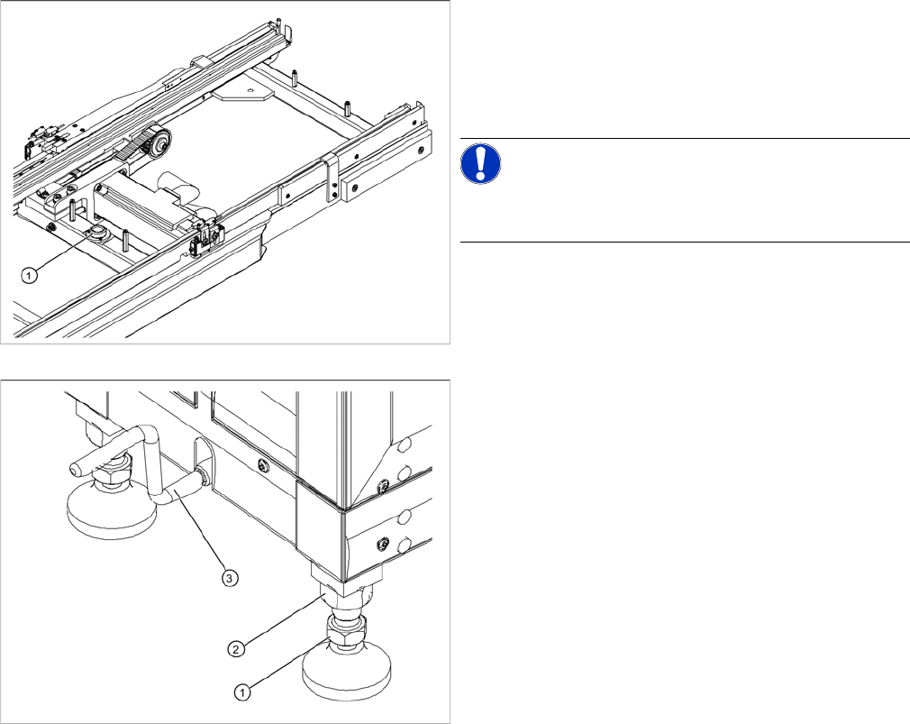
Aligning the WPC5/WPC6
1. Circular spirit level
► Check the position of the WPC5/WPC6 with the help
of the integrated spirit level (1), which is between the
two rails of the feeder axis.
NOTICE!
The cover on the feed axis arms is not shown in the dia-
gram.
1. Foot with 30 mm nut
2. 36 mm locknut
3. Hexagonal shaft (crank handle)
► If the WPC5/WPC6 is not level, use a 30 mm and 36
mm open-ended wrench to adjust the feet in turn, un-
til more than half of the bubble is in the circle of the
spirit level.
Setting up and Commissioning
Setting Up the Module 4.2.3 Switch on the WPC5/WPC6
34 Operating Manual SIPLACE WPC5/WPC6
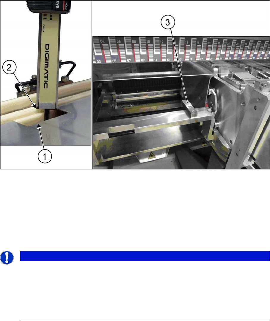
Setting the exact height of the WPC5/WPC6
► Use a measuring scale to adjust the WPC5/WPC6 to the correct height through the opening (1) on
the cover plate of the feed axis.
► Use the gauge to measure the height of the WPC5/WPC6 from the white sliding surface of the waffle
pack tray carrier (2) to the aluminum block on the changeover table insert (3). The correct height
should be 87 ± 0.5 mm.
► If the height is outside the specified value, adjust each foot accordingly to lower or raise the WPC5/
WPC6 to the correct height.
4.2.3
4.2.3 Switch on the WPC5/WPC6
Switch on the WPC5/WPC6
Start up sequence with two WPCs
4.2.4
4.2.4 Undocking the WPC5/WPC6
Undocking the WPC5/WPC6
Preparatory Steps
► Go to Manual operations => Entire machine functions and perform a Overall reference run.
► Perform a WPC reference run. To do this, select Manual operations => Subsystems => WPC and
click on Reference run.
► Use the software to move the lifting axis of the WPC5/WPC6 into the transport position. To do this,
select the Move into transport position button. The WPC5/WPC6 will be moved to a defined position,
from which it can be safely transported.
► Disconnect the WPC5/WPC6 from the power supply and the data supply.
NOTICE
Start up sequence with two WPCs
In case of two WPCs on one machine the start up sequence has to be observed. Otherwise
some errors (CAN switch errors) may occur.
► Always switch on the WPCs first and then the machine.
► On machines of type SX1/SX2 as well as DX1/DX2 with two WPCs, both WPCs must be
switched on simultaneously with the machine (within 12 sec.).
If not, the CAN switch switches into the "error" state.