00196622-03_OM_WPC5_6_EN.pdf - 第43页
Operator Tasks 5.5.1 Basic View Maintenance and Service Operating Manual SIPLACE WPC5/WPC 6 43 5.4 5 . 4 M a in t e n a n c e a n d S e r v ic e Maintenance and Service See also the document " Maintenanc e guide WPC…
Operator Tasks
Non-Stop Module at WPC6 5.3.1 Refilling with the Non-Stop Modul
42 Operating Manual SIPLACE WPC5/WPC6
5.3.1
5.3.1 Refilling with the Non-Stop Modul
Refilling with the Non-Stop Modul
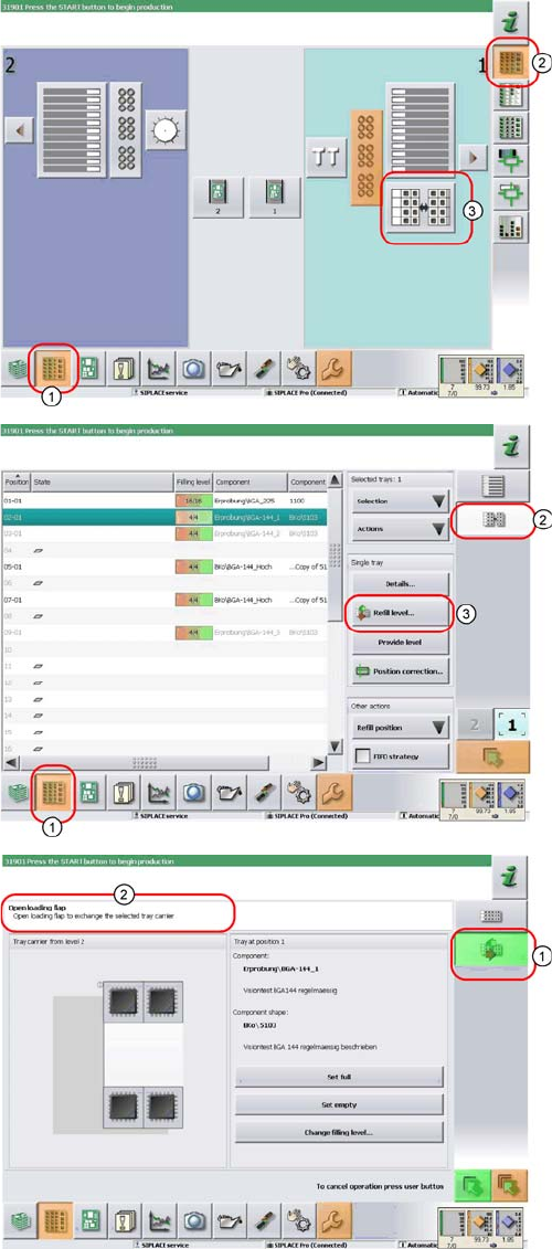
► In the tool bar of the main view click on the icon (1) for
the functions Feeder, Locations….
► Click on the icon (2). The user interface will switch to
the view Functions > Locations > WPC.
► Click on the icon (3) for the WPC5/WPC6 at the rele-
vant location (location 1 here).
The Setup > Locations > WPC view will be shown for
the selected Location.
► Click on the icon (2).
► Click on the Refill level… (3) icon.
The view for refilling the Non-Stop Module will be dis-
played.
► The icon (1) shows, that one tray carrier is transport-
ed in or out of the Non-Stop Module.
► You see the current actions in the indicator area (2).
Observe the hints and follow the instructions provid-
ed.
► Press the operating button to start the actions with
the Non-Stop Module. Check the status of the button
(continuous light, blinking light or no light) and carry
out the actions allowed.
Operator Tasks
5.5.1 Basic View Maintenance and Service
Operating Manual SIPLACE WPC5/WPC6 43
5.4
5.4 Maintenance and Service
Maintenance and Service
See also the document "Maintenance guide WPC4/WPC5WPC6" [item no. 00195347-xx].
5.5
5.5 Functions at the Station Computer (SR703.xx)
Functions at the Station Computer (SR703.xx)
5.5.1
5.5.1 Basic View
Basic View
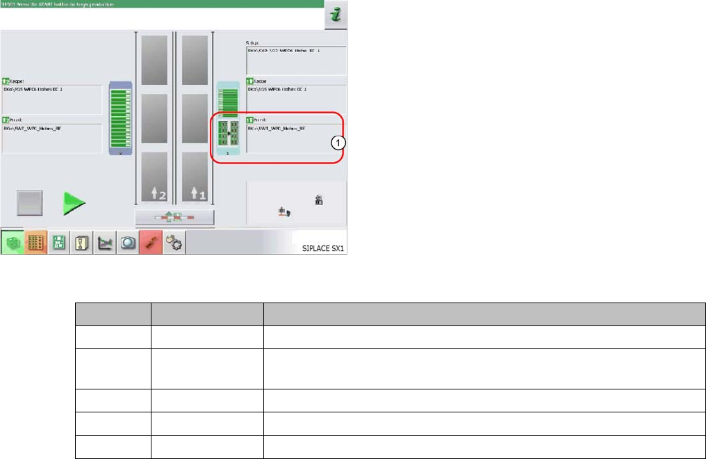
The WPC icon (1) can be displayed in various colors in the basic view. These mean:
The display applies equally to the WPC and to the feeder modules, which are set up on the remaining
feeder locations, next to the WPC.
The basic view shows the SIPLACE machine from above.
The PCB conveyor runs through the center. The locations
are positioned on the right and left. The location of the
WPC is shown as item (1) in this example.
WPC color Component color Meaning
Gray - - - No component in WPC / feeder module configured or no setup defined.
Gray Green A setup is present and one or more components are defined for this lo-
cation.
Gray Red / green Empty waffle pack trays/ tracks in WPC / feeder module
Red Red / green Track error at this location (WPC / feeder module)
Yellow Red / green Production was continued although the WPC is in the refill position.
Operator Tasks
Functions at the Station Computer (SR703.xx) 5.5.2 WPC5 Functions
44 Operating Manual SIPLACE WPC5/WPC6
5.5.2
5.5.2 WPC5 Functions
WPC5 Functions
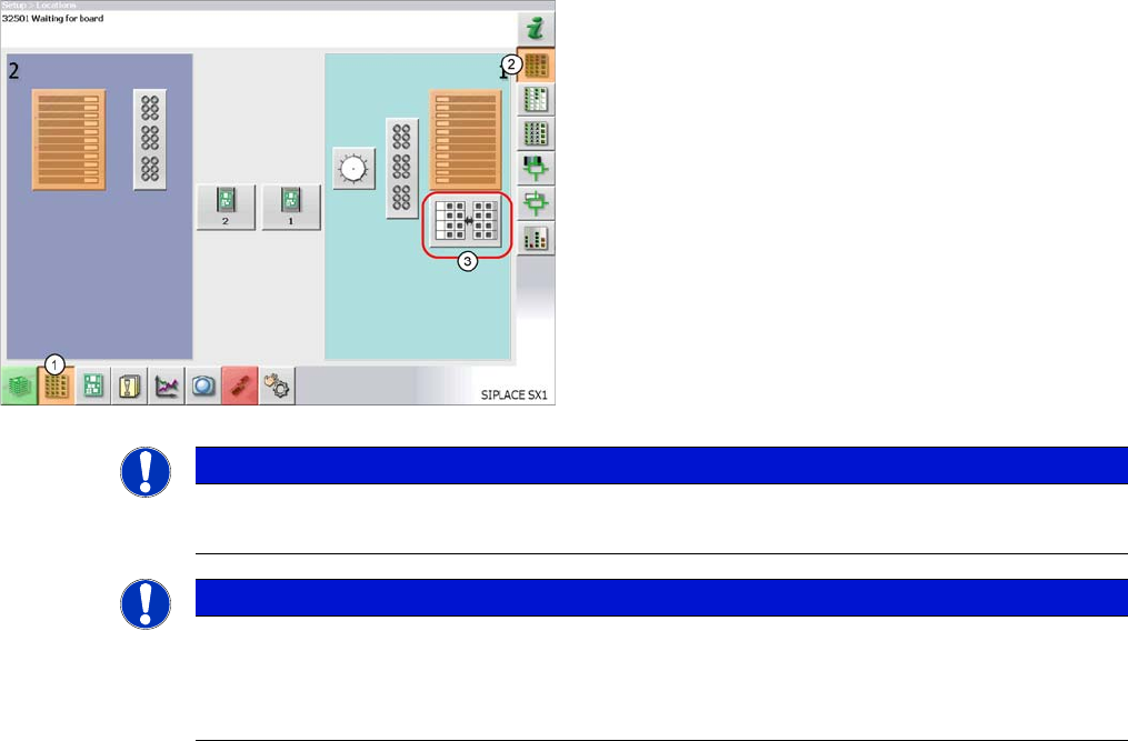
► In the tool bar of the main view click on the icon (1) for
the functions Feeder, Locations….
► Click on the icon (2). The user interface will switch to
the view Functions > Locations > WPC.
► Click on the icon (3) for the WPC5 at the relevant lo-
cation (location 1 here).
The Setup > Locations > WPC view will be shown for
the selected Location.
NOTICE
WPC icon
The icon for the WPC5 will only be shown for the location if a WPC5 is really present there.
NOTICE
Main view
If there is a setup available for the WPC5, this will be shown as an icon in the diagram of the
relevant WPC5 in the main view.
If you click on this, the WPC view will be opened for the WPC5 at the location.