M6ex_ServiceManual_e.pdf - 第72页
4 Electrical Section 4-6 ■ Details tab The signal output operation allow s an actuator to move. Make sure non-operators keep a safe distance from the mounter before starting the operation. Action: ① Click the cell corres…
4 Electrical Section
4-5
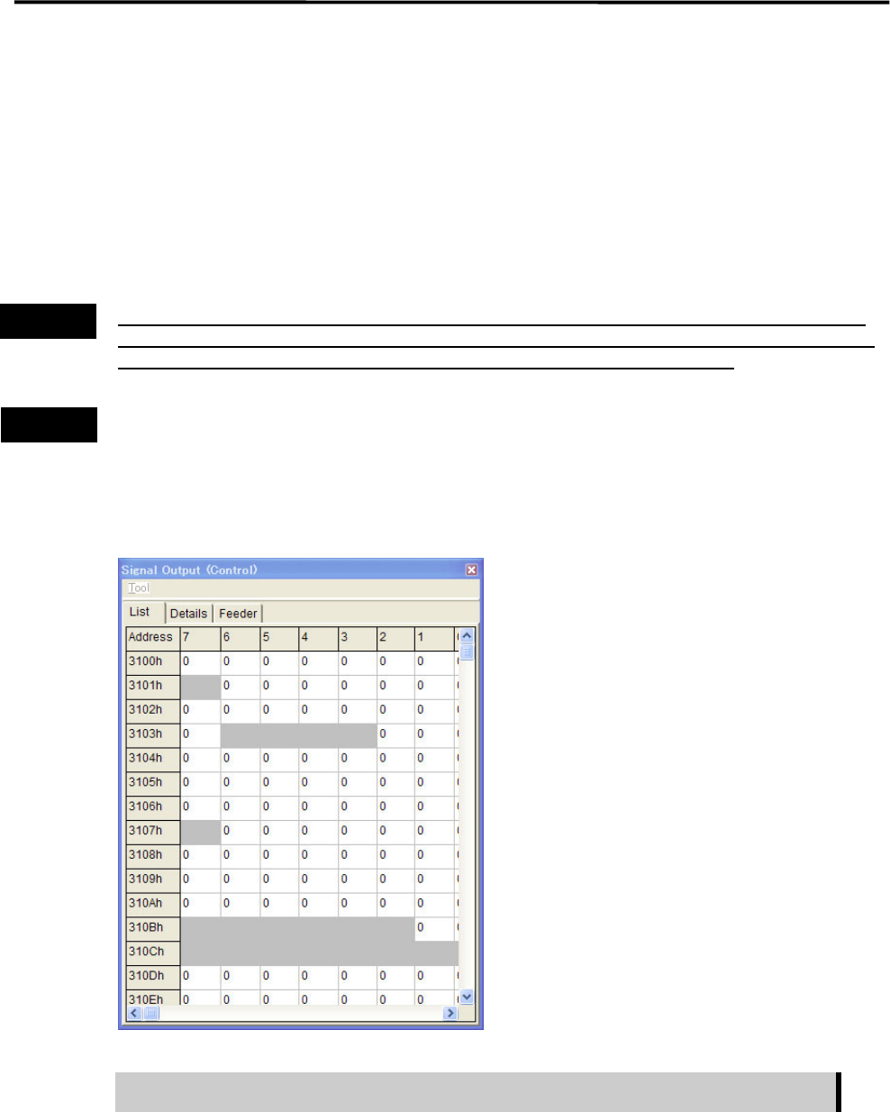
Signal Output Control
The Signal Output (Control) window serves as controls to turn on or off actuators. “1” in the window
indicates On state, “0” Off state. “0” and “1” toggle as you click on it, and the corresponding actuator is
turned on or off simultaneously. This operation allows you to check actuator movement in troubleshooting.
When an actuator moves properly in this operation, its sensor responds and the Signal Input (Monitor)
window shows the real-time result. The combination of an address and bit number (0-7) represents a signal.
The name of each signal is shown in the Details tab.
Turning on/off signal output in the Signal Output (Control) window allows an actuator to move. When
executing this operation, do not stick head, hands, or other parts of the body inside the mounter. Serious
injury can result. Also make sure non-operators are a safe distance from the mounter.
Before performing signal output on/off operation, make sure no foreign obstacles are left in the mounter or
tray feeder. Otherwise, costly machine damage can occur.
Menu: Manual>Signal I/O>SignalOutput(Control)
■ List tab
The signal output operation allows an actuator to move. Make sure non-operators
keep a safe distance from the mounter before starting the operation.
Action:
① Click the cell corresponding to the desired actuator.
② The actuator is turned on or off and the display changes accordingly.
Note: Sampling cycle can be specified in Tool>SamplingCycle.
Warning
Caution
4 Electrical Section
4-6
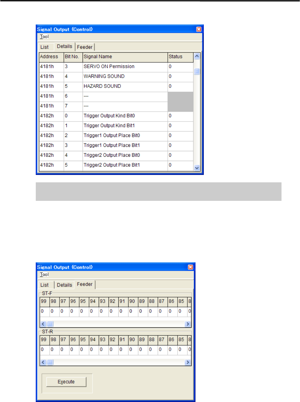
■ Details tab
The signal output operation allows an actuator to move. Make sure non-operators
keep a safe distance from the mounter before starting the operation.
Action:
① Click the cell corresponding to the desired actuator.
② The actuator is turned on or off and the display changes accordingly.
■ Feeder tab
This tab allows you to operate the tape feeders set in the front and rear feeder banks.
Action:
① Scroll left or right to display the desired feeder number.
② Click “0” of the desired feeder number “0” switches to “1”.
③ Click <Execute> button allows the feeder for one feeder indexing.
4 Electrical Section
4-7
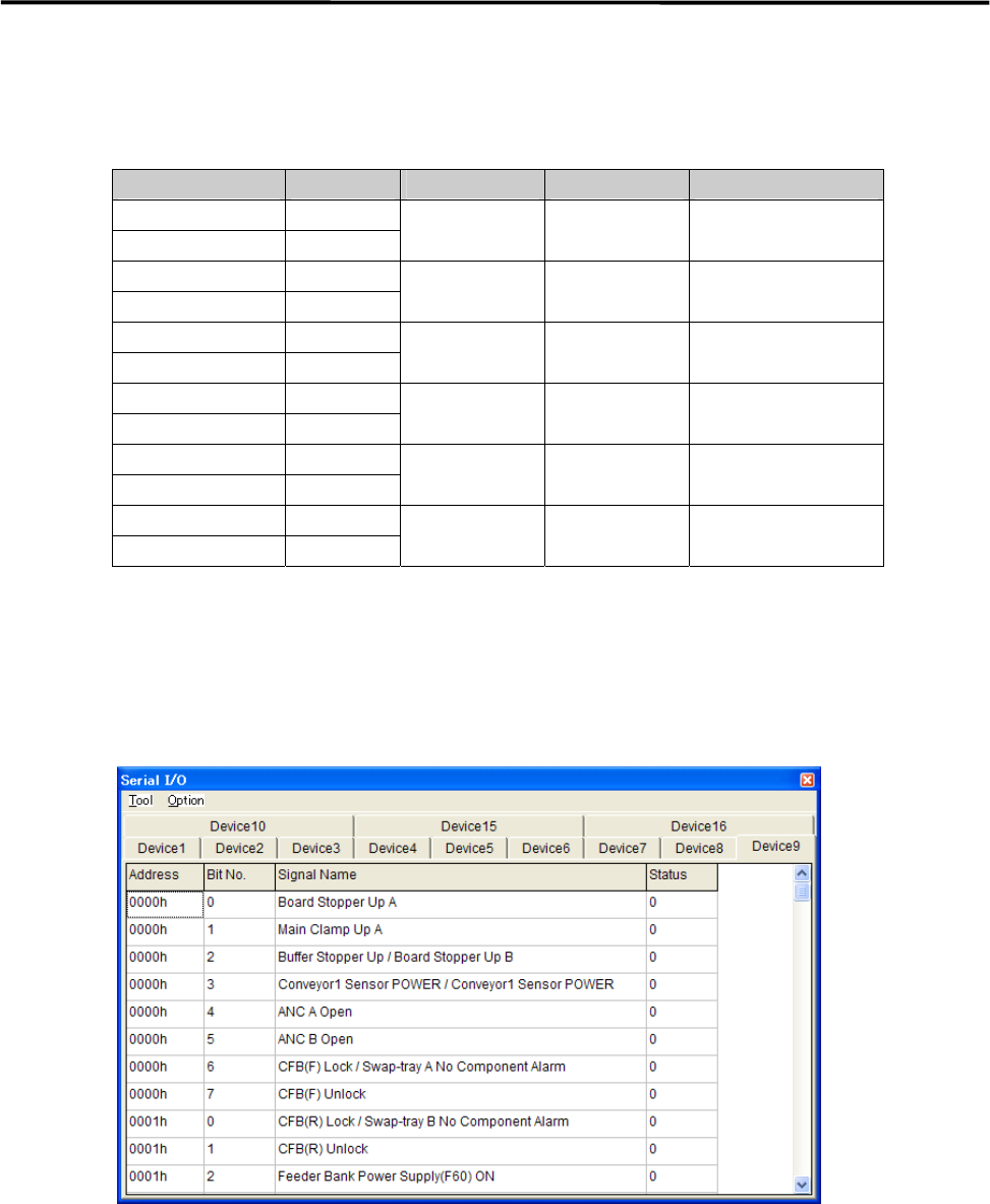
Serial I/O
■ Serial I/O List
Device No. DO/DI I/O port Main function Communication board
Device1 DO control
Device2 DI monitor
CDA2 CN1 Head operation HIO11
Device3 DO control
Device4 DI monitor
CDA2 CN2
Device5 DO control
Device6 DI monitor
CDA2 CN3 Front operation SWG6 (F)
Device7 DO control
Device8 DI monitor
CDA2 CN4 Rear operation SWG6 (R)
Device9 DO control
Device10 DI monitor
CDA2 CN5 Conveyor CIO7
Device11 DO control
Device12 DI monitor
CDA2 CN6 Tray feeder MXR
Action:
① Click the cell corresponding to the desired actuator.
② At the same time you click the cell, the display changes 1(On) or 0(Off), and the actuator moves
accordingly.
Example:
■ Moving Up and Down the Board Stopper
① Select Manual> Signal I/O to open [Serial I/O] window.
② Select [Device9] tab.
③ Click [State] of [Board Stopper Up A] cell, Status changes “0” to “1” and the board stopper lifts. At this
time, confirm that State of [Board Stopper Up A (0002h)] in [Device10] switches from “0” to “1”.
To move down the board stopper, click [State] of [Board Stopper Up A] in [Device9]. And State changes
“1” to “0”. At this time, State of [Board Stopper Up A (0002h)] in [Device10] switches from “1” to “0”.