PC150-Manual-REV-A-2.pdf - 第11页
PC150 Valve Manual Revision A / Jan uary 202 2 Page 11 of 26 Maintena nce Interval Action Daily • Examine the m aterial o utlets f or c ontami nation a n d cur ed m aterial. Weekly • Ex amine Part A and B materi al cont …
PC150 Valve Manual
Revision A / January 2022
Page 10 of 26
Shutdown Procedure
1. Reduce the material pressure to the system to 0 psi.
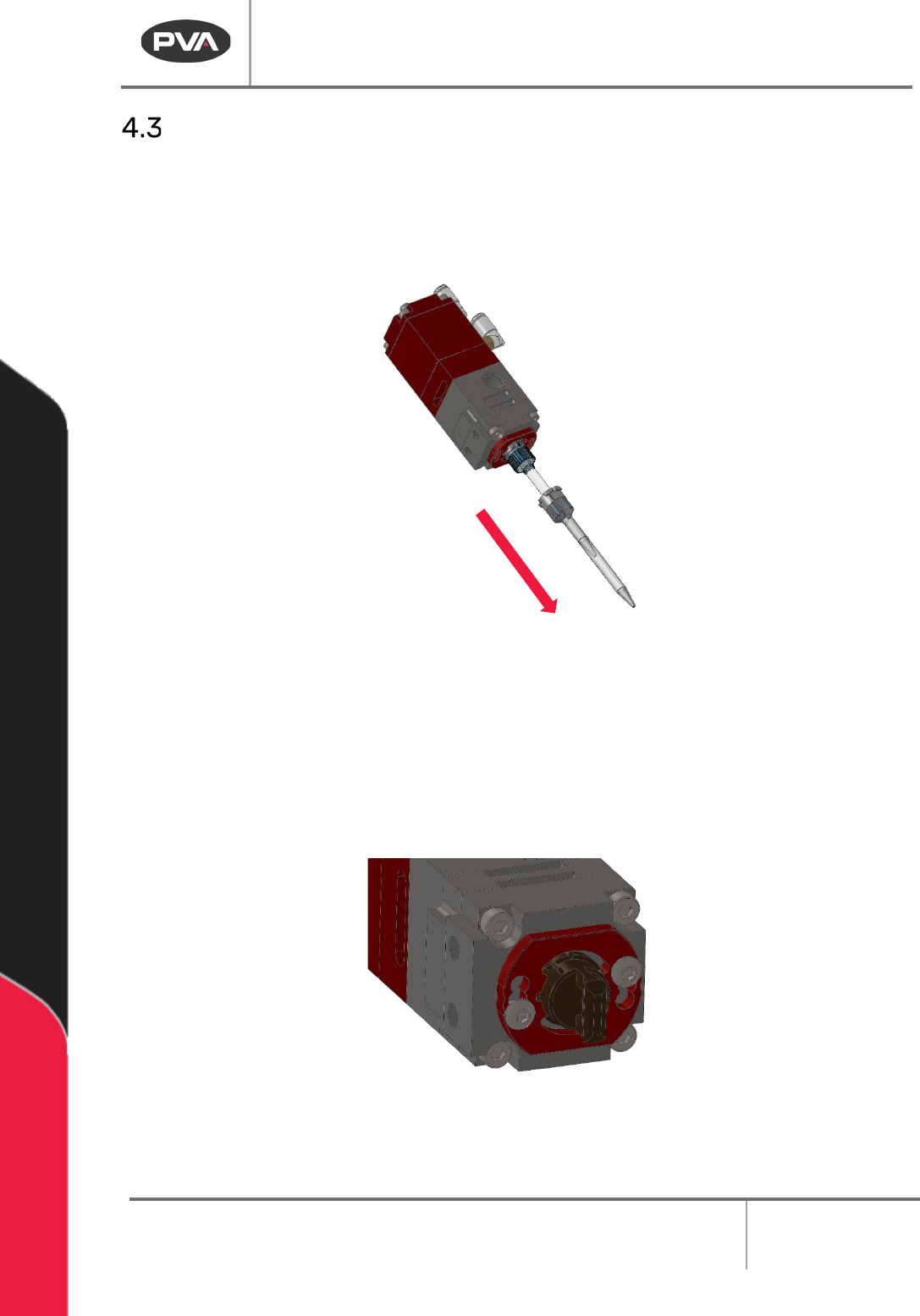
2. Push and turn the static mixer counterclockwise 90 degrees to remove it. Discard
the static mixer.
Figure 5: Remove the Static Mixer
3. Purge fresh material through the valve until both material streams are completely
clean and have no cross-contamination (20-30 seconds).
4. Clean all material off the manifold nozzle.
5. Install the night cap onto the manifold nozzle.
Figure 6: Install Cap
6. Reduce the material pressure for materials A and B to 0 psi.
PC150 Valve Manual
Revision A / January 2022
Page 11 of 26
Maintenance
Interval
Action
Daily
• Examine the material outlets for contamination and cured material.
Weekly
• Examine Part A and B material containers or cartridges for signs of cured
or dried material.
Before you perform any maintenance on this valve, ensure there is a spare parts kit. If any
parts have wear or damage, replace them with new parts from the kit.
Disassemble the Wetted Section of the Valve
This section illustrates how to disassemble the wetted portion of PC150 valves. If you
have questions about procedure steps, parts, or content, contact PVA’s Customer
Service department.
Procedure
Place the valve sections, seals, parts, and screws in a compatible solvent to soak if material
can be seen on them. Do not combine materials A and B or they will cure. Examine all parts
for wear and damage. Replace parts if necessary.
1. Reduce the system pressure to 0 psi.
2. Disconnect the material and air fittings.
3. Disconnect the valve from the dispense system.
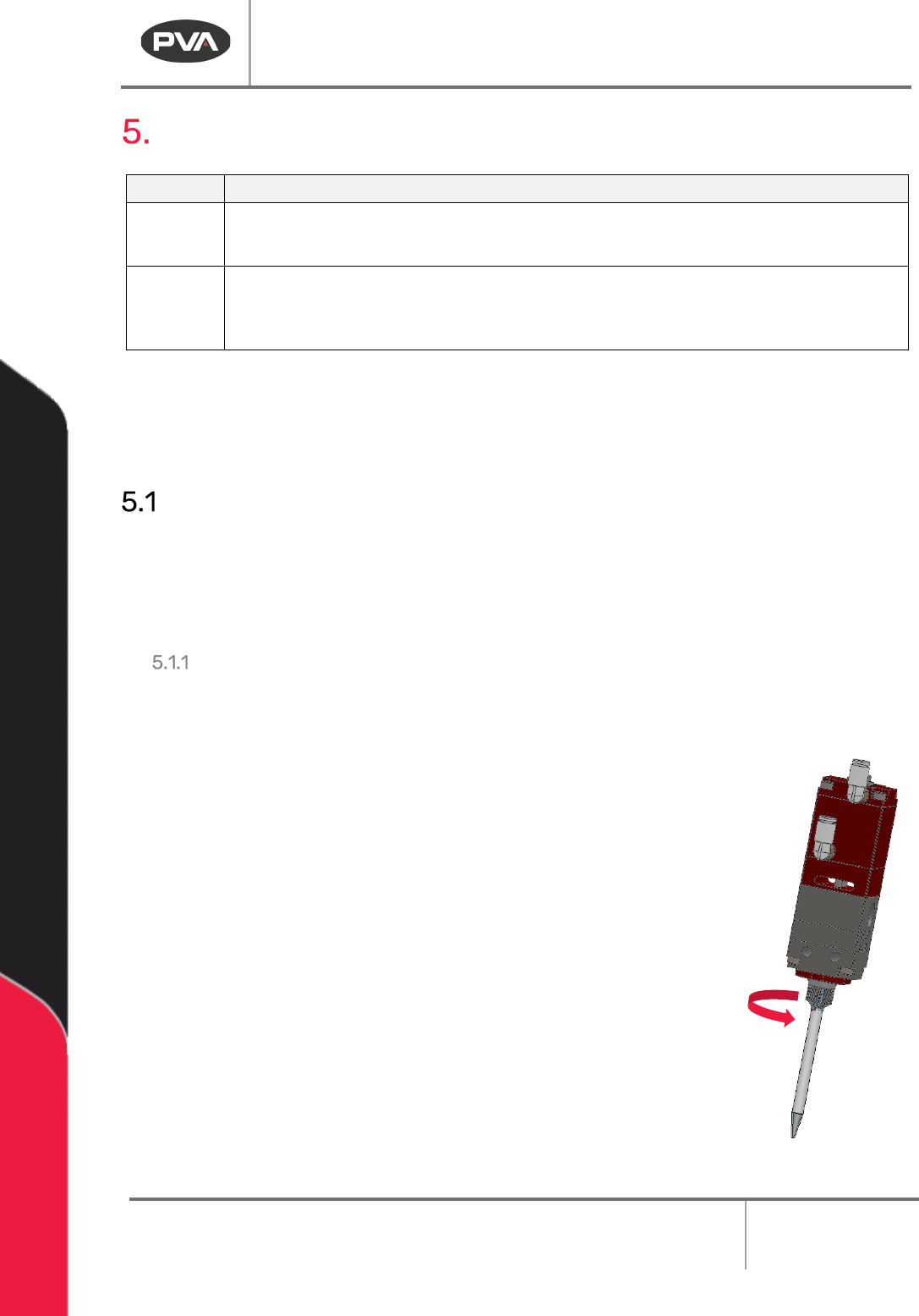
4. Turn the mixer retaining ring counterclockwise until it is free from
the mixer retainer.
Figure 7: Remove Mixer Retainer
PC150 Valve Manual
Revision A / January 2022
Page 12 of 26
5. Remove the static mixer (refer to Figure 5).
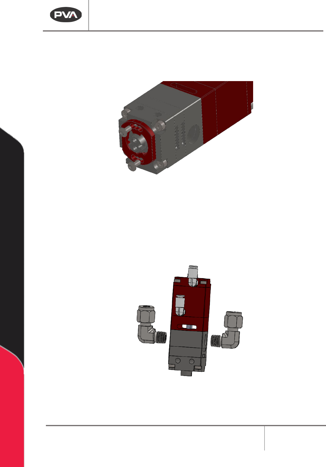
Figure 8: Remove the Mixer Retainer Screws
7. Remove the mixer retainer.
8. Use a crescent wrench to turn the two (2) material fittings counterclockwise to
remove them.
Figure 9: Remove the Material Fittings
9. Use a hex wrench to remove the four (4) socket head cap screws from the fluid
section.