PC150-Manual-REV-A-2.pdf - 第8页
PC150 Valve Manual Revision A / Jan uary 202 2 Page 8 of 26 Valve Ope rat ion Startup 1. Inst all the val ve pneu matically as shown in Section 1.4 and set the air pre ssure that operates the valve betwee n 80 - 100 psi …
PC150 Valve Manual
Revision A / January 2022
Page 7 of 26
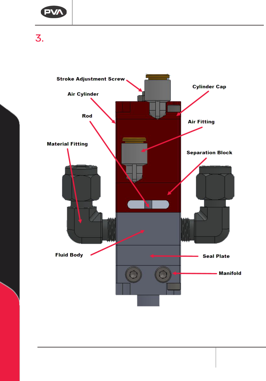
Overview
Before you operate the valve, know the valve components. Examine the valve components
shown below for safe and correct operation.
Figure 2: PC150 Overview

PC150 Valve Manual
Revision A / January 2022
Page 8 of 26
Valve Operation
Startup
1. Install the valve pneumatically as shown in Section 1.4 and set the air pressure
that operates the valve between 80-100 psi.
2. Make sure that the valve is not pointed at anyone and cycle the valve several
times. When the valve cycles correctly, you will hear the piston hit the stroke
adjustment screw and the rods can be seen going up and down in the center.
Note: If the valve does not cycle correctly, refer to Section 9.
3. Connect the material delivery system to the valve. The Part A material connects
on the left side, the Part B material connects on the right side.
4. Cycle the valve open to bleed. Part A and B materials should start to flow
separately out of the fluid manifold.
5. Bleed the valve until all the air is released and the material releases smoothly
without any breaks in the flow. Any break in the flow of the material indicates
there is still air in the system.
Note: Part A and B materials may not start to dispense from the valve at the same
time; flow depends on the necessary mix ratio.
6. To get the necessary amount of snuff back, use a 2.5 mm hex wrench to adjust
the stroke adjustment screw. Turn the stroke adjustment screw clockwise to
decrease the amount of snuff back or counterclockwise to increase the amount
of snuff back. If the stroke adjustment screw is turned down too far, the valve
will not close and material will leak from the manifold nozzle.
Note: As a best practice, it is recommended to turn the stroke adjustment screw
clockwise until material starts to leak from the valve manifold when under
pressure, and then turn the stroke adjustment screw a ½ turn counterclockwise
or until it does not leak.
7. When the snuff back is set, use an adjustable wrench to tighten the jam nut
against the sealing washer and cylinder cap to lock it in place.
Note: Refer to Section 9 for any other issues.
PC150 Valve Manual
Revision A / January 2022
Page 9 of 26
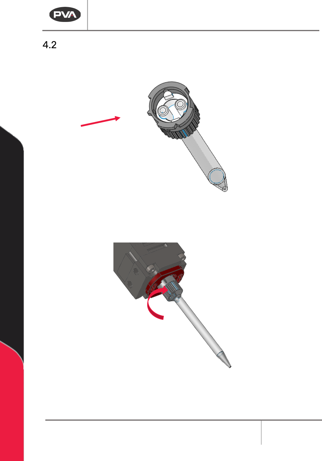
Install the Static Mixer
1. Align the notch in the collar with the corresponding notch in the static mixer and
insert static mixer into the retaining collar.
Figure 3: Static Mixer Notch
2. Push and turn the static mixer clockwise 90 degrees to engage it. The static mixer
will be hard to turn. Make sure it is fully engaged.
Figure 4: Install the Static Mixer
3. Purge the valve to fill the static mixer with material.