PC150-Manual-REV-A-2.pdf - 第18页
PC150 Valve Manual Revision A / Jan uary 202 2 Page 18 of 26 PC150 Se ries Refere nce PC150 Bill of Materials Item Part Number Description Qty 1 SHCS M3x0.5 X 8 SOCKET HEAD CAP SCREW 2 2 SHCS M3x0.5 X 35 SOCKET HEAD CAP …
PC150 Valve Manual
Revision A / January 2022
Page 17 of 26
8. Align the assembled fluid section to the bottom of the air cylinder assembly and
install four (4) socket head cap screws with the correct thread locker.
Figure 19: Assemble the Air and Fluid Sections
9. Install the mixer retainer with two (2) button head cap screws with the correct
thread locker applied.
Figure 20: Install the Mixer Retainer
10. Install Teflon tape on the 1/8 NPT fluid fittings.
11. Install the necessary 1/8 NPT fluid fittings.
12. Install the static mixer, refer to Section 4.2.

PC150 Valve Manual
Revision A / January 2022
Page 18 of 26
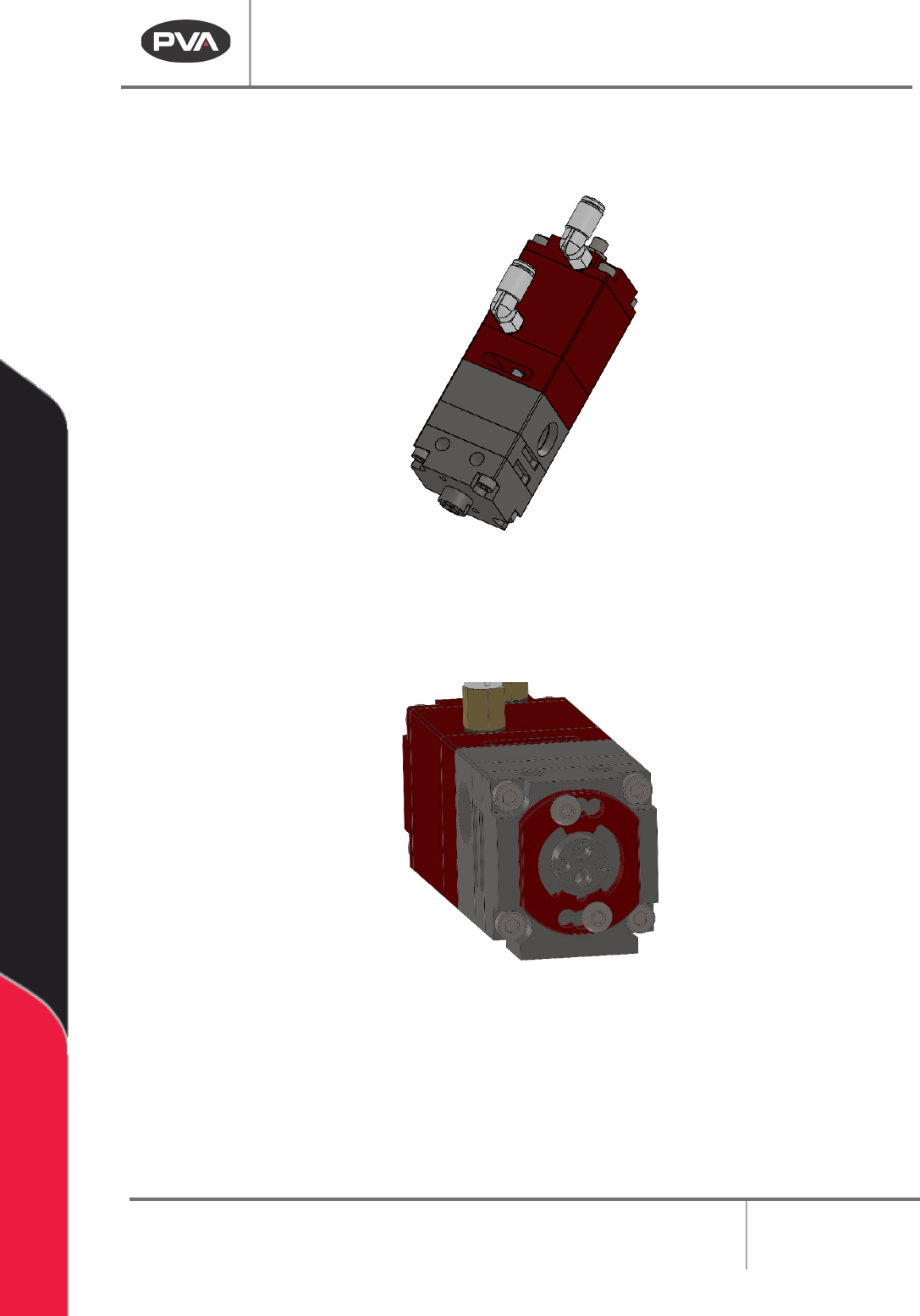
PC150 Series Reference
PC150 Bill of Materials
Item Part Number Description Qty
1 SHCS M3x0.5 X 8 SOCKET HEAD CAP SCREW 2
2 SHCS M3x0.5 X 35 SOCKET HEAD CAP SCREW 8
3
B18.3.6M - M5 x 0.8 x 20 Hex
Socket Flat Pt. SS
SET SCREW 1
4
B18.2.4.5M - Hex jam
nut, M5 x 0.8 --D-N
1
5 65075822 SEALING WASHER, #10/M5 1
6 KQ2L04-M5A
FITTING, ELBOW, 4MM HOSE X M5
THREAD
2
7 VLV-006K O-RING, -006, KALREZ 4
8 VLV-011K O-RING, -011, KALREZ 4
9 VLV-006B O-RING, -006, BUNA-N 2
10 VLV-117B O-RING, -117, BUNA-N 2
11 614-8574-1
PCS150 FLUID BODY, LOWER
SECTION
1
12 614-8576-1
PCS150 FLUID BODY, CENTER
SECTION
1
13 614-8578-1
PCS150 FLUID BODDY, UPPER
SECTION
1
14 614-8580-1 PCS150 AIR BODY 1
15 614-8581-1 PCS150 PISTON 1
16 614-8584-1 PC150 AIR CAP 1
18 214-5448 BUSHING, 0.126 ID, 0.245 LG 2
17 614-8592-1 PCS150 ROD 2
18 214-5448 BUSHING, 0.126 ID, 0.245 LG 2
19 614-8601-1 PCS100 ROD GUIDE 1
20 214-7976 MIXER RETAINER 1
21 101515 NIGHT CAP 1
Figure 21: PC150 Bill of Materials
PC150 Valve Manual
Revision A / January 2022
Page 19 of 26
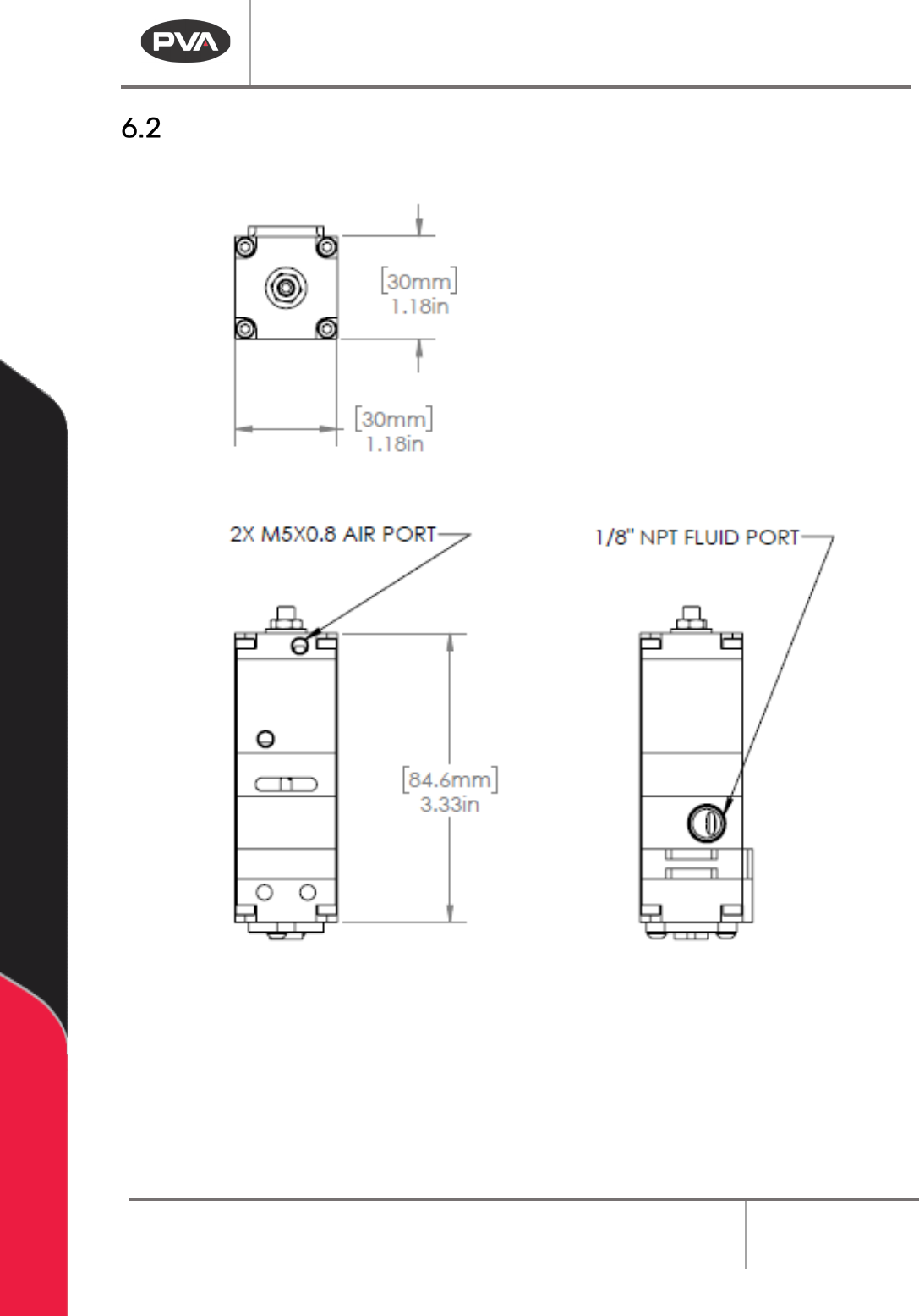
PC150 Series Mechanical Drawings
Figure 22: Mechanical Drawing