PC150-Manual-REV-A-2.pdf - 第16页
PC150 Valve Manual Revision A / Jan uary 202 2 Page 16 of 26 4. Install t wo (2 ) VLV - 006 K O - ring s in th e top si de of fl uid bo dy. Figure 17 : O - rings in the Top of the Fluid B ody 5. Align the m anifold , sea…
PC150 Valve Manual
Revision A / January 2022
Page 15 of 26
Assemble the Valve
This section shows how to assemble the PC150 series valve.
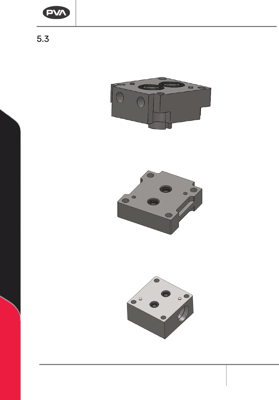
1. Install two (2) VLV-011K O-rings in the top of manifold.
Figure 14: O-rings in the Manifold
2. Install two (2) VLV-006K O-rings in the top side of seal plate.
Figure 15: O-rings in the Seal Plate
3. Install two (2) VLV-001K O-rings in the bottom side of the fluid body.
Figure 16: O-rings in the Bottom of the Fluid Body
PC150 Valve Manual
Revision A / January 2022
Page 16 of 26
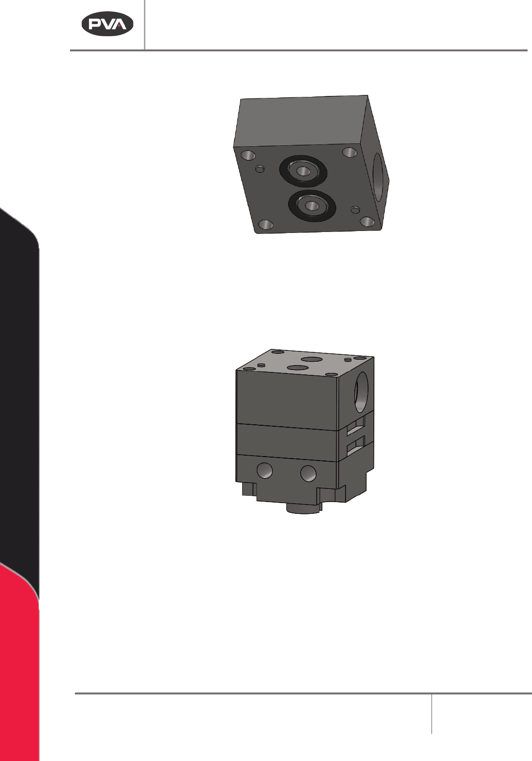
4. Install two (2) VLV-006K O-rings in the top side of fluid body.
Figure 17: O-rings in the Top of the Fluid Body
5. Align the manifold, seal plate, and fluid body on top of one another.
6. Make sure all O-rings are still seated.
Figure 18: Fluid Assembly
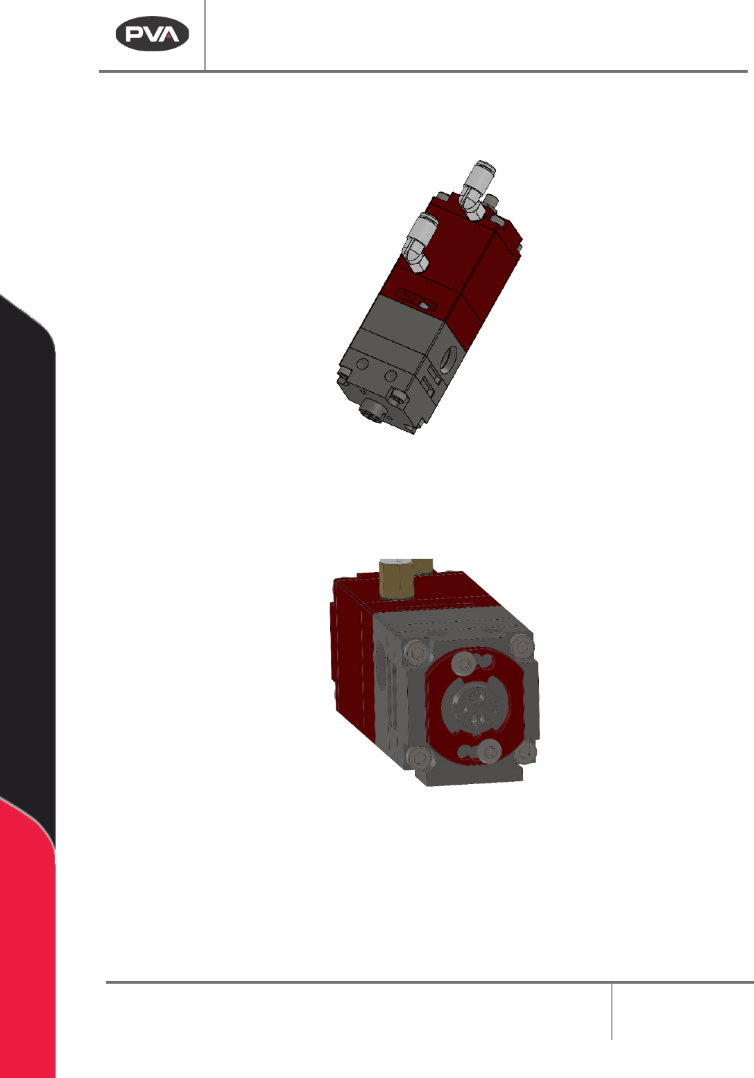
7. Apply Loctite 222 to the ends of four (4) socket head cap screws and two (2)
button head cap screws.
PC150 Valve Manual
Revision A / January 2022
Page 17 of 26
8. Align the assembled fluid section to the bottom of the air cylinder assembly and
install four (4) socket head cap screws with the correct thread locker.
Figure 19: Assemble the Air and Fluid Sections
9. Install the mixer retainer with two (2) button head cap screws with the correct
thread locker applied.
Figure 20: Install the Mixer Retainer
10. Install Teflon tape on the 1/8 NPT fluid fittings.
11. Install the necessary 1/8 NPT fluid fittings.
12. Install the static mixer, refer to Section 4.2.