PC150-Manual-REV-A-2.pdf - 第15页
PC150 Valve Manual Revision A / Jan uary 202 2 Page 15 of 26 Assemble the Valve This section shows how to assembl e the PC 150 seri es valve. 1. Install t wo (2 ) VLV - 011K O - ring s in the top of manif old. Figure 14 …
PC150 Valve Manual
Revision A / January 2022
Page 14 of 26
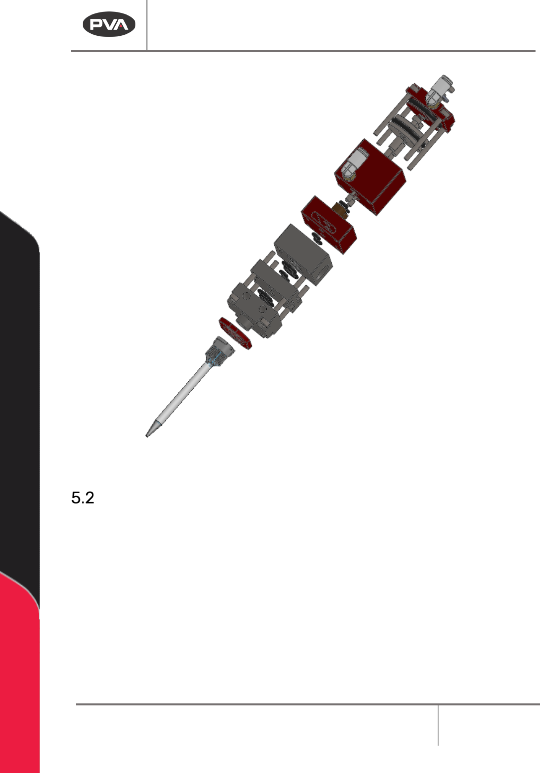
Figure 13: Fully Disassembled Fluid Section
Clean the Disassembled Valve
Clean every wetted part completely with a compatible solvent, lint-free towels, and cotton
tipped applicators to clean the valve wetted section. This includes the ends of the rods. Do
not mix material A and B or the material may cure. Wear protective gloves. Do not get
material or solvent on your skin.
Make sure all grease and material are removed from the valve components before the valve
is assembled again. All O-rings, seals, and screws should be cleaned and replaced if
damaged.
PC150 Valve Manual
Revision A / January 2022
Page 15 of 26
Assemble the Valve
This section shows how to assemble the PC150 series valve.
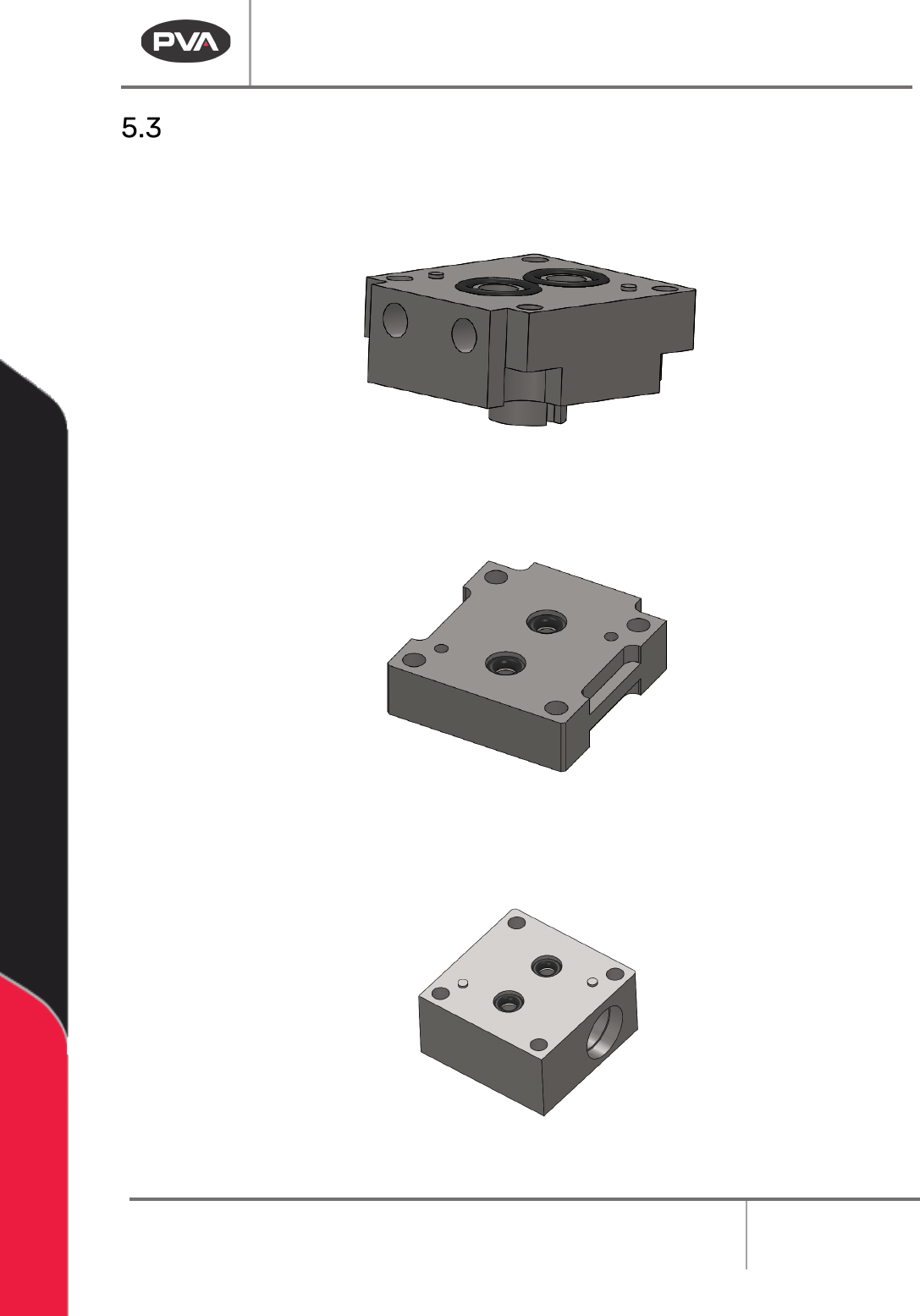
1. Install two (2) VLV-011K O-rings in the top of manifold.
Figure 14: O-rings in the Manifold
2. Install two (2) VLV-006K O-rings in the top side of seal plate.
Figure 15: O-rings in the Seal Plate
3. Install two (2) VLV-001K O-rings in the bottom side of the fluid body.
Figure 16: O-rings in the Bottom of the Fluid Body
PC150 Valve Manual
Revision A / January 2022
Page 16 of 26
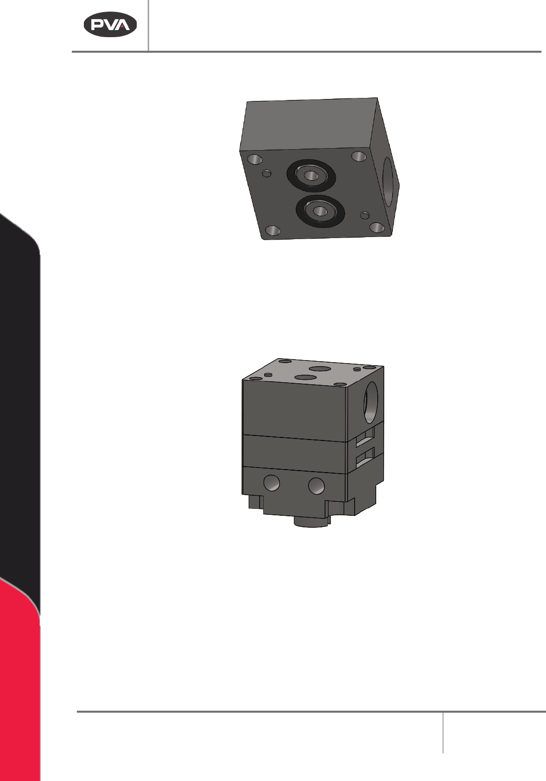
4. Install two (2) VLV-006K O-rings in the top side of fluid body.
Figure 17: O-rings in the Top of the Fluid Body
5. Align the manifold, seal plate, and fluid body on top of one another.
6. Make sure all O-rings are still seated.
Figure 18: Fluid Assembly
7. Apply Loctite 222 to the ends of four (4) socket head cap screws and two (2)
button head cap screws.