5OM-1732-003Y_F8_资料.pdf - 第133页
5OM-1732 4-1-47 1206-001 搬送 IO 线路板 008 部 PCB Stopper 1 Lower Limit Detection PCB Stopper 1 Upper Limit Detection PCB Stopper 2 Lower Limit Detection PCB Stopper 2 Upper Limit Detection PCB Stopper 3 Lower Limit Detection…
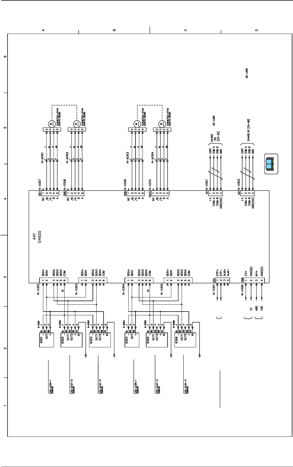
5OM-1732
4-1-461208-002
搬送驱动 (D4920) 部
PCB Detection Sensor 1
PCB Detection Sensor 2
Deceleration/Stop Sensor 1
Placement Section
Deceleration/Stop Sensor 2
Placement Section
Deceleration/Stop Sensor 3
Placement Section
Deceleration/Stop Sensor 4
Placement Section
Note a
B Lane : U08 Transfer I/O X0817 [C6-4B]
A Lane : U14 Transfer I/O X1417 [C7-4B]
Note a
B Lane : U08 Transfer I/O X0818 [C6-4B]
A Lane : U14 Transfer I/O X1418 [C7-4B]
Note a
B Lane : U08 Transfer I/O X0819 [C6-4B]
A Lane : U14 Transfer I/O X1419 [C7-4B]
Note a
B Lane : U08 Transfer I/O X0820 [C6-4B]
A Lane : U14 Transfer I/O X1420 [C7-4B]
A Lane : X10153 [18-5B]
B Lane : X10154 [18-5C]
[02-3C] DC24V(24A3)
[02-3C] DC48V(48D)
Control Power
Main Power
Conveyor Emergency Stop
U01 Intensive I/O
CN2(Axis 1)
CN3(Axis 2)
CN4(Axis 3)
CN5(Axis 4)
(Sensor Input)
Axis 1
Axis 2
Axis 3
Axis 4
[There is no placement destination. ]
Note b
Note c
24A3 2
Do 1
24A6
24A6
Note
(a) Connection Destination is different in lane A from that in Lane B.
(b) Not connected in the case of Buffer OP not mounted
(c) Connection Destination in the case of Backup OP mounted
24A6
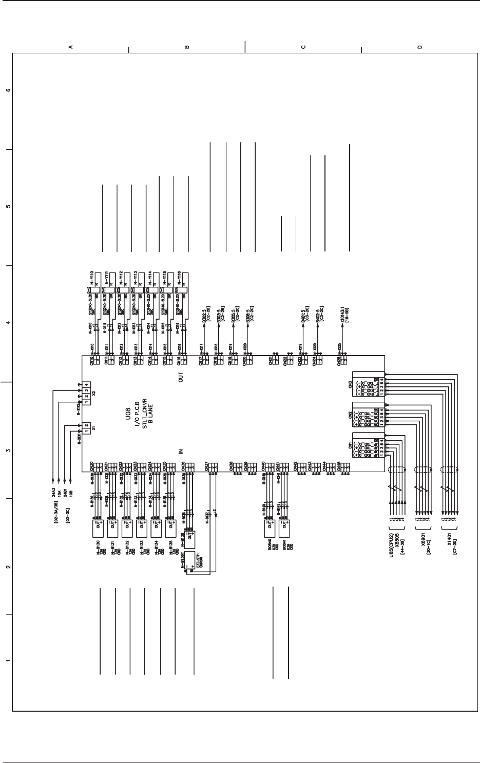
5OM-1732
4-1-471206-001
搬送 IO 线路板 008 部
PCB Stopper 1 Lower Limit Detection
PCB Stopper 1 Upper Limit Detection
PCB Stopper 2 Lower Limit Detection
PCB Stopper 2 Upper Limit Detection
PCB Stopper 3 Lower Limit Detection
PCB Stopper 3 Upper Limit Detection
Movable Chute Back up Pin Sensor 1
S1 Fixed Z-Clamp Lower Limit Detection
S2 Fixed Z-Clamp Lower Limit Detection
Feeder (Rear)
U14 (Transfer IO)
Note
Note 1. The drain cable should be connected
to the connector case.
FG (Connector Case)
FG (Connector Case)
FG (Connector Case)
Note 1 Note 1 Note 1
PCB Stop Sensor Input Section 5 Remote
PCB Stop Sensor Input Section 4 Remote
PCB Stop Sensor Input Section 3 Remote
PCB Stop Sensor Input Section 1 Remote
PCB Stop Sensor Input Section 1 Remote
PCB Stop Sensor Input Section 6 Remote
S1 Z-Clamp Cylinder Valve 1
(A : Down)
S1 Z-Clamp Cylinder Valve 2
(B : Up)
S2 Z-Clamp Cylinder Valve 2
(B : Up)
PCB Stopper 1 UP/DOWN Valve
PCB Stopper 2 UP/DOWN Valve
PCB Stopper 3 UP/DOWN Valve
PCB Stop Sensor Placement Section 1 Remote
PCB Stop Sensor Placement Section 2 Remote
PCB Stop Sensor Placement Section 3 Remote
PCB Stop Sensor Placement Section 4 Remote
PCB Stop Sensor Input Section 5 Remote
PCB Stop Sensor Input Section 6 Remote
Backup Pin Conveyor Emergency Stop (UC18)
S2 Z-Clamp Cylinder Valve 1
(A : Down)
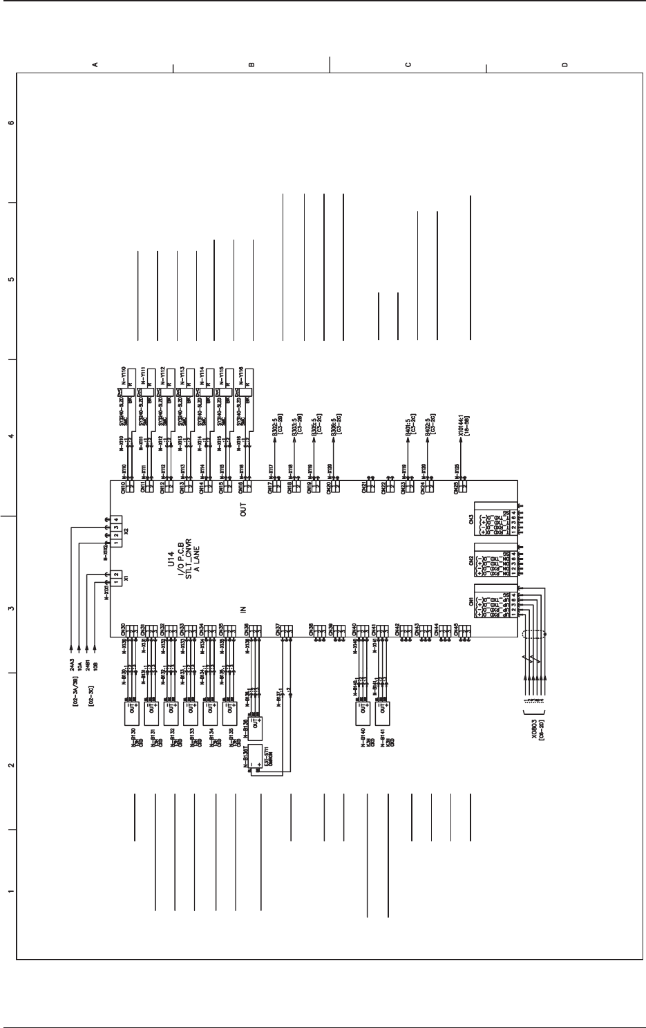
5OM-1732
4-1-48
1206-001
搬送 IO 线路板 U14 部
PCB Stopper 1 Lower Limit Detection
PCB Stopper 1 Upper Limit Detection
PCB Stopper 2 Lower Limit Detection
PCB Stopper 2 Upper Limit Detection
PCB Stopper 3 Lower Limit Detection
PCB Stopper 3 Upper Limit Detection
Movable Chute Back up Pin Sensor 1
S1 Fixed Z-Clamp Lower Limit Detection
S2 Fixed Z-Clamp Lower Limit Detection
Note
Note 1. The drain cable should be connected
to the connector case.
U08 (Transfer IO)
FG (Connector Case)
FG (Connector Case)
FG (Connector Case)
Note 1
PCB Stop Sensor Input Section 5 Remote
PCB Stop Sensor Input Section 4 Remote
PCB Stop Sensor Input Section 3 Remote
PCB Stop Sensor Input Section 1 Remote
PCB Stop Sensor Input Section 1 Remote
PCB Stop Sensor Input Section 6 Remote
S1 Z-Clamp Cylinder Valve 1
(A : Down)
S1 Z-Clamp Cylinder Valve 2
(B : Up)
S2 Z-Clamp Cylinder Valve 2
(B : Up)
PCB Stopper 1 UP/DOWN Valve
PCB Stopper 2 UP/DOWN Valve
PCB Stopper 3 UP/DOWN Valve
PCB Stop Sensor Placement Section 1 Remote
PCB Stop Sensor Placement Section 2 Remote
PCB Stop Sensor Placement Section 3 Remote
PCB Stop Sensor Placement Section 4 Remote
PCB Stop Sensor Input Section 5 Remote
PCB Stop Sensor Input Section 6 Remote
Backup Pin Conveyor Emergency Stop (UC18)
S2 Z-Clamp Cylinder Valve 1
(A : Down)