00198654-01_UM_Nozzle_Cleaning_Station_EN.pdf - 第37页
4 Setting up and commissioning 4.2 Configuration when delivered User Manual SIPLACE Nozzle Cleaning Station 09/2019 37 4.2.5 Transporting the placement machine in the shipping crate or on the pallet Fig.19: Transportati…
4 Setting up and commissioning
4.2 Configuration when delivered
36 User Manual SIPLACE Nozzle Cleaning Station 09/2019
4.2 Configuration when delivered
4.2.1 Services
As a special service, SIPLACE offers to realize the complete integration of your nozzle cleaning
station in your facility. With our extensive expertise and by using the right tools and equipment, we
can ensure that the installation process runs smoothly and efficiently. However, this will require you
to clarify the infrastructure aspects in advance and make any necessary changes at your produc-
tion facility.
4.2.2 Shipping packaging
The SIPLACE NCS and cleaning options are delivered in separate packages. The NCS is packed
in a wooden crate and the cleaning options are packed in cardboard with foam inlays.
CAUTION
Damage from condensation
To avoid damage from condensation, only open the packaging once the NCS or the com-
ponents have adjusted to the ambient temperatures. This can take up to 24 hours.
4.2.3 Checking a delivery
► Check the delivery for damage.
► Unpack the machine and the accessories and check the delivery for completeness (reference
delivery note).
► Document the results in the installation report /acceptance protocol.
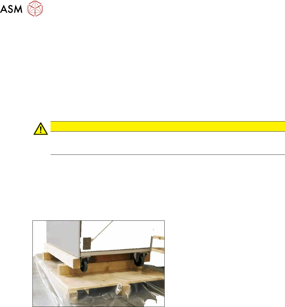
4.2.4 Shipping braces
Fig.18: Transportation crate/pallet - shipping braces
The SIPLACE NCS gets delivered seated on
two wooden bars. In addition, a wooden
bracket is screwed to each side to prevent it
slipping.
4 Setting up and commissioning
4.2 Configuration when delivered
User Manual SIPLACE Nozzle Cleaning Station 09/2019 37
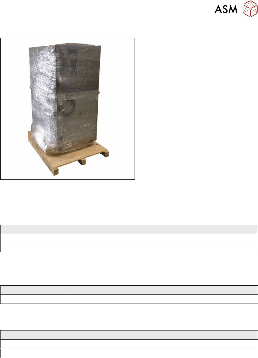
4.2.5 Transporting the placement machine in the shipping crate or on the pallet
Fig.19: Transportation crate/pallet - attachment points for
transportation with the fork-lift
The transport crate or pallet should only be
lifted at the side.
► Transport the SIPLACE NCS on the
pallet / the crate as near as possible to
the final site of use.
4.2.5.1 Shipping packaging dimensions
The dimensions of the pallets and wooden crates are listed in the following table:
Machine (L x W x H)
Pallet 1410 mm x 1210 mm
Wooden crate 1500 mm x 1300 mm x 2200
4.2.5.2 Weight of machine when ready for dispatch
The following table contains the weights of the placement machines prepared for dispatch, includ-
ing packaging.
Machine Dispatch
SIPLACE NCS 350 kg
4.2.5.3 Transportation equipment for transporting the placement machine in the packaging
Use a pallet truck / fork-lift truck with the following specification to carry the placement machine:
Machine Dispatch
Fork length Min. 1200 mm
Lifting power Min. 500 kg
4 Setting up and commissioning
4.3 Infrastructure at the installation location
38 User Manual SIPLACE Nozzle Cleaning Station 09/2019
4.3 Infrastructure at the installation location
The floor on which the nozzle cleaning station is installed must be firm and level, as a tilt could af-
fect the tightness of the system when the nozzle cleaning station is operated. The following are
suitable provided that the floor loading parameters, etc., are not exceeded:
●
Reinforced concrete ceiling constructions, e.g. ceilings in production halls
●
Reinforced concrete floor slabs, e.g. concrete floors in production halls without a basement
●
Rooms with double floors, provided that a stable foundation is included in the space between
them. The same setup conditions apply to this intermediate foundation, which can be made
from steel girders or concrete.
4.3.1 Ground levelness
The floor underneath the nozzle cleaning station may not exceed an incline of 0.63%. This corres-
ponds to an incline of 5 mm over a distance of 800 mm.
4.3.2 Machine weight and floor surface load
The machine weight and floor surface load can be found in section 3.3.1 "Technical data - dimen-
sions and weight" [}28].
4.3.3 Compressed air supply
4.3.3.1 Checking the compressed air supply
Check whether the compressed air supply complies with the prescribed placement machine spe-
cifications (see table in section 3.2.2 "Environmental conditions for operation" [}27]).
Record the compressed air characteristics at the installation location.
WARNING
Risk of injuries!
Risk of injuries from pressurized compressed air lines.
NEVER detach compressed air lines while they are still pressurized.
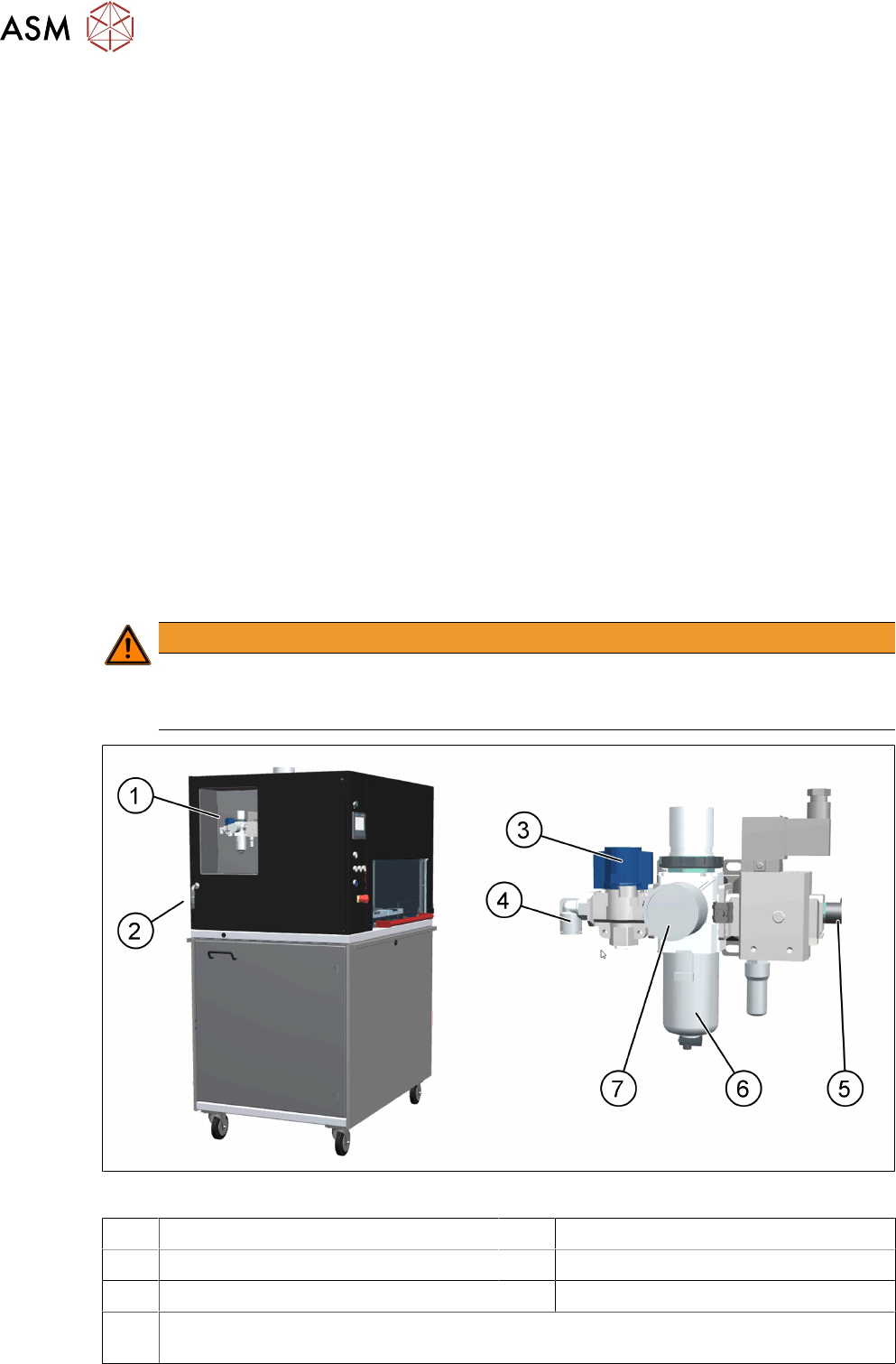
Fig.20: NCS - compressed air unit
1 Location of the compressed air unit 2 Compressed air connection
3 Stop valve in the "CLOSED" position 4 Compressed air supply
5 Compressed air supply for cleaning 6 Compressed air filter
7 Manometer for the nozzle cleaning station supply pressure
Target pressure: 0.50 ± 0.01MPa, 5.0 ± 0.1bar (display range 0–1.0MPa, 0–10bar)