00198654-01_UM_Nozzle_Cleaning_Station_EN.pdf - 第57页
7 The HMI operating panel 7.4 Manual control screens User Manual SIPLACE Nozzle Cleaning Station 09/2019 57 7.4.1 Example of a tip cleaning screen The manual control is only enabled when applicable conditions have been m…
7 The HMI operating panel
7.4 Manual control screens
56 User Manual SIPLACE Nozzle Cleaning Station 09/2019
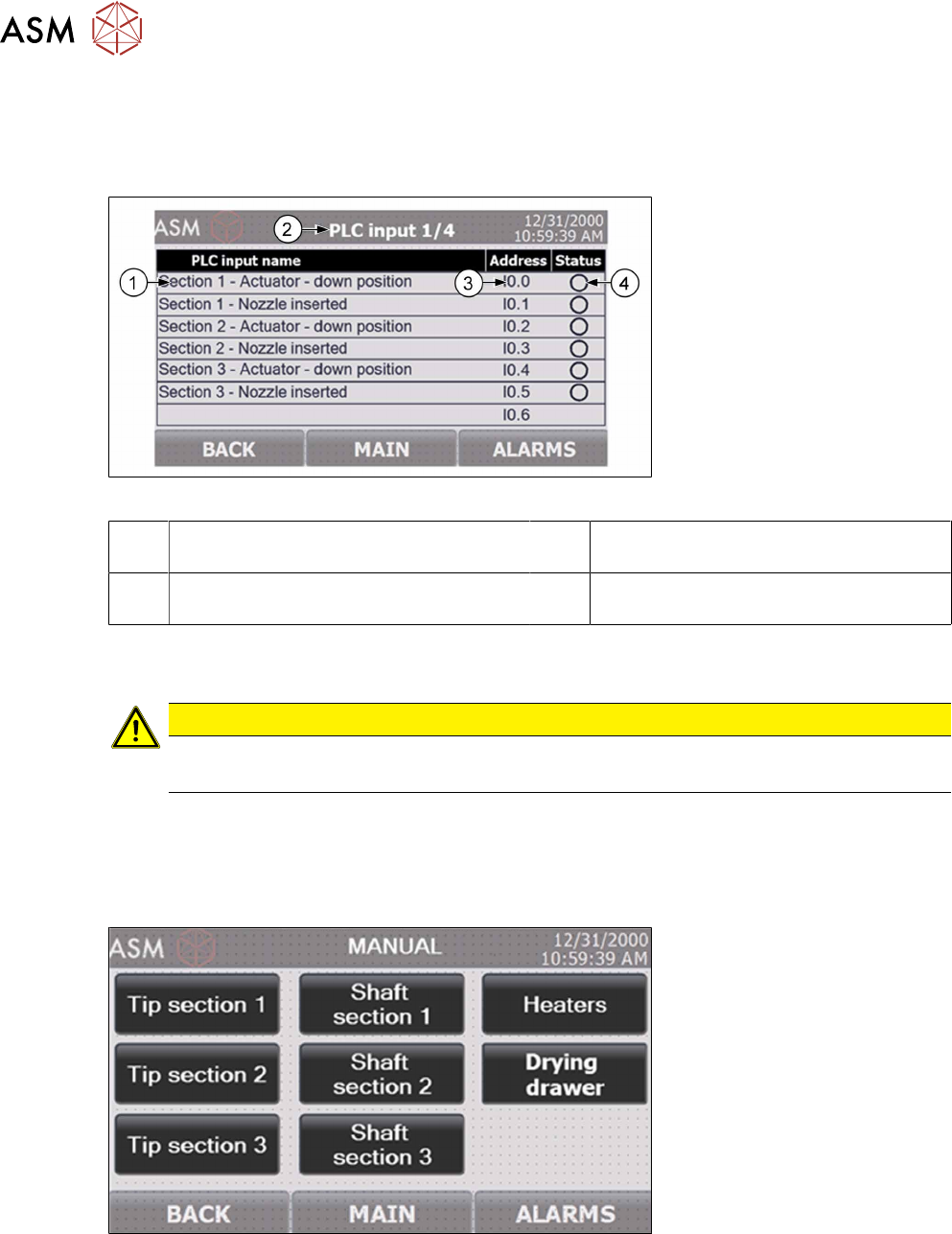
7.3.3 PLC input/output status screen
The Status screen provides access to the overviews of all PLC inputs and outputs. The status of
each input and output helps diagnose and read the status of the machine sensors. Each next
screen is laid out very similar to the example shown below.
Fig.42: NCS - HMI PLC input screen
1 PLC input designation 2 Header: shows the number of the PLC
input/output sub-screen
3 The PLC address of the specific input/
output
4 Input/output status: green is for active
(high signal)
7.4 Manual control screens
CAUTION
Risk of damage!
The operation using the manual mode should be done by training personnel only.
To activate the manual mode, stop the processing cycle in progress by pressing and holding the re-
spective START button. The manual mode is opened by entering any of the Manual screens. Note,
however, that this requires activating the machine's safety system and closing all access doors. Ac-
cess to the Manual screens requires the operator to log in with a security password; this prevents
unauthorized users from manually operating the machine's components.
Fig.43: NCS - HMI main manual control screen
7 The HMI operating panel
7.4 Manual control screens
User Manual SIPLACE Nozzle Cleaning Station 09/2019 57
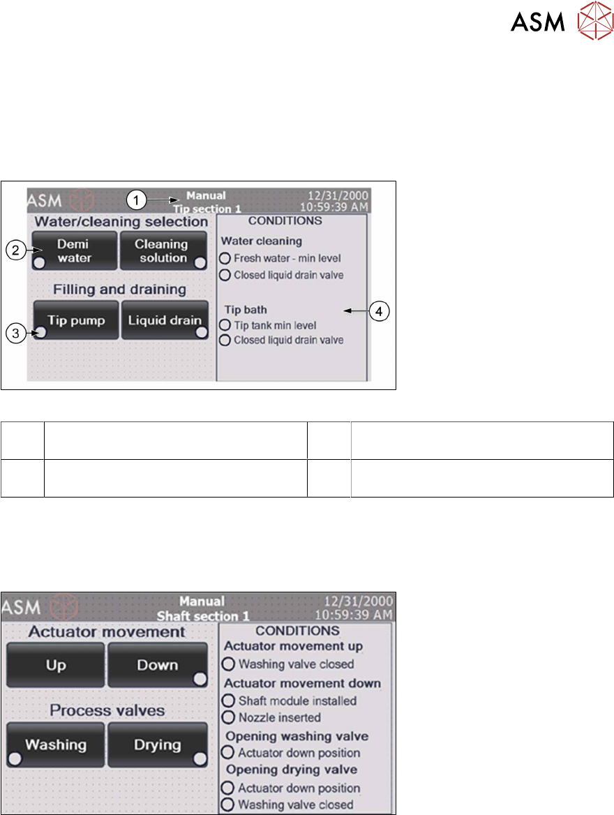
7.4.1 Example of a tip cleaning screen
The manual control is only enabled when applicable conditions have been met. This prevents the
machine from inadvertent damage or flooding by operator's manual actions. The conditions to be
met to enable a specific function are listed in the right-hand part of the screen.
In the tip section screen, you can run the fluid cycle (demi or cleaning agent), drain or fill the tip
cleaning module reservoir and start the fluid circulation pump (tip pump).
Fig.44: NCS - HMI tip cleaning manual control screen
1 Manually controlled processing section
name
2 Component operation buttons
3 Component activation indicator 4 List of conditions for activating the com-
ponents
7.4.2 Example of a shaft cleaning screen
The shaft cleaning menu is similar to the tip cleaning menu. You can manually move the actuator,
open the cleaning or the drying valve. The shaft cleaning valve and the drying valve can only be
opened with the actuator in the down position and they cannot be opened simultaneously.
Fig.45: NCS - HMI shaft cleaning manual control screen
7 The HMI operating panel
7.5 Parameter setting screens
58 User Manual SIPLACE Nozzle Cleaning Station 09/2019
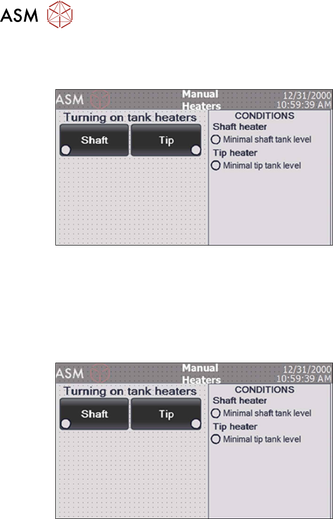
7.4.3 Heater controls
In the heater menu both tip cleaning and shaft cleaning heating can be activated provided there is
sufficient liquid in the container.
Fig.46: NCS - HMI heating manual control screen
7.5 Parameter setting screens
Pressing "Parameters" on the MENU screen opens the processing cycle parameter settings. The
parameter screen requires process engineer access rights. Upon pressing parameters, the HMI op-
erating panel prompts you to enter the correct security password.
The screen enables access to the settings of the processing times and the processing bath (tank)
temperature settings.
Fig.47: NCS - HMI parameter settings screen