00198654-01_UM_Nozzle_Cleaning_Station_EN.pdf - 第55页
7 The HMI operating panel 7.3 Status screens User Manual SIPLACE Nozzle Cleaning Station 09/2019 55 7.3.1 Automatic mode conditions screen The condition screens show the data of all prerequisite states and actions to be …
7 The HMI operating panel
7.2 Menu screen
54 User Manual SIPLACE Nozzle Cleaning Station 09/2019
7.2 Menu screen
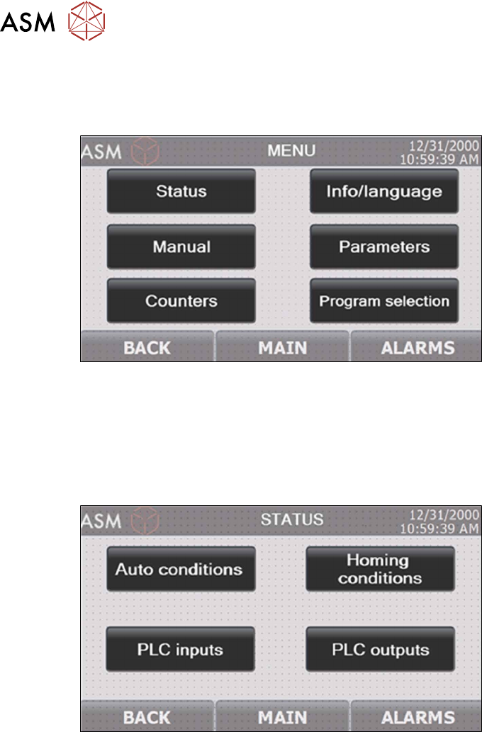
The menu screen enables the navigating of the specific screen subgroups. Pressing "Parameter"
or "Manual" displays the prompt for entering the security password.
Fig.38: NCS - HMI menu screen
7.3 Status screens
The status screens are categorized in two groups:
► The screens of machine operation preconditions
► The PLC input and output status screens
Fig.39: NCS - HMI main machine status screen
7 The HMI operating panel
7.3 Status screens
User Manual SIPLACE Nozzle Cleaning Station 09/2019 55
7.3.1 Automatic mode conditions screen
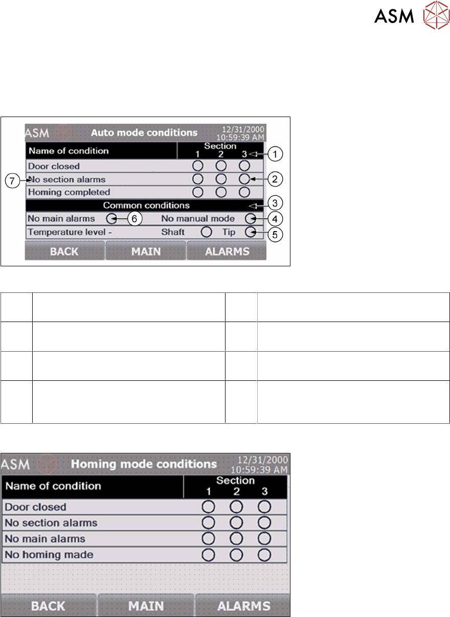
The condition screens show the data of all prerequisite states and actions to be met and completed
in order to enable starting the machine processing cycle. These screens can be displayed with
manual commands in the STATUS screen, or automatically, whenever the operator attempts to run
a processing cycle with one or more prerequisites (conditions) not met.
Fig.40: NCS - HMI automatic mode conditions screen
1 The processing section number to which
the conditions below apply
2 Condition status: green if met
3 The pane with the conditions common to
all three processing sections
4 Manual mode not active indicator
5 Processing bath temperature reached
indicator
6 No machine alarms active indicator
7 The name of the condition to be met
These conditions apply to individual pro-
cessing sections.
7.3.2 Homing mode conditions screen
Fig.41: NCS - HMI homing mode conditions screen
7 The HMI operating panel
7.4 Manual control screens
56 User Manual SIPLACE Nozzle Cleaning Station 09/2019
7.3.3 PLC input/output status screen
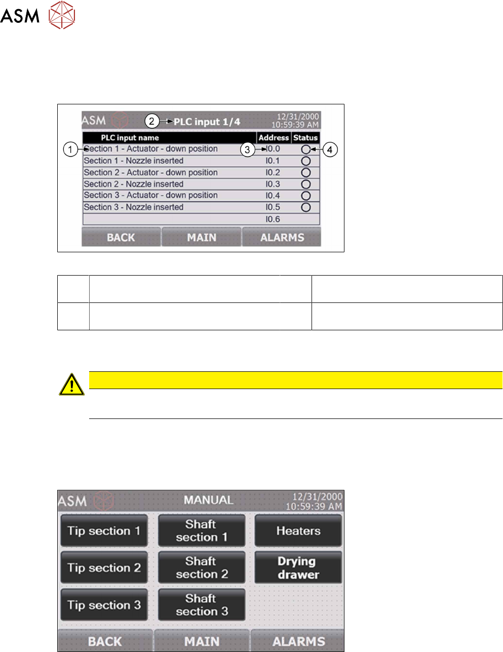
The Status screen provides access to the overviews of all PLC inputs and outputs. The status of
each input and output helps diagnose and read the status of the machine sensors. Each next
screen is laid out very similar to the example shown below.
Fig.42: NCS - HMI PLC input screen
1 PLC input designation 2 Header: shows the number of the PLC
input/output sub-screen
3 The PLC address of the specific input/
output
4 Input/output status: green is for active
(high signal)
7.4 Manual control screens
CAUTION
Risk of damage!
The operation using the manual mode should be done by training personnel only.
To activate the manual mode, stop the processing cycle in progress by pressing and holding the re-
spective START button. The manual mode is opened by entering any of the Manual screens. Note,
however, that this requires activating the machine's safety system and closing all access doors. Ac-
cess to the Manual screens requires the operator to log in with a security password; this prevents
unauthorized users from manually operating the machine's components.
Fig.43: NCS - HMI main manual control screen