192866 Issue 4 - Reel to Reel Manual LoRes.pdf - 第18页
TECHNICAL REFERENCE ADJUSTMENTS AND SETTINGS 1.8 Reel to Reel Manual Chapter Issue 1, Apr 15 14. From the lef t hand side of the machine, slacken the two home vane securing screws. 15. If the rising t able needs to be hi…
TECHNICAL REFERENCE
ADJUSTMENTS AND SETTINGS
Chapter Issue 1, Apr 15 Reel to Reel Manual 1.7
ADJUSTMENTS AND SETTINGS
Rising Table Home Setting
WARNING
HOT SURFACES. THE SURFACE OF THIS COMPONENT OR SURROUNDING
AREA MAY BECOME HOT DURING PROLONGED OPERATION. CARE TO BE
TAKEN WHEN WORKING IN THE VICINITY OF THIS COMPONENT.
1. Remove the screen from the machine.
2. Select Maintenance.
3. Select Diagnostics.
4. Use Next or Previous to highlight Rising Table.
5. Select Select Module.
6. Ensure Home Rising Table is highlighted.
7. Select Run Diagnost.
8. Remove the left hand side safety cover.
9. Open the front printhead cover.
10. Fit the screen so that the rear edge is further forward than the rear edge of
the vacuum top plate.
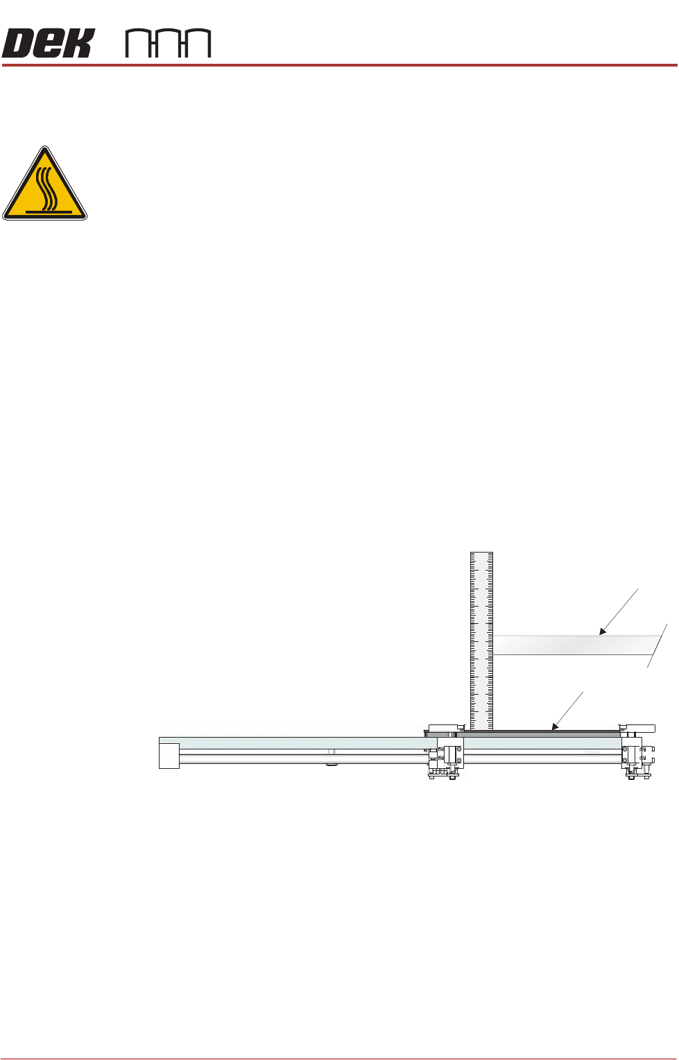
11. Using a steel rule, measure the distance between the underneath of the
screen frame and the top of the vacuum top plate.
12. Check that the distance is 128mm -0mm/+2mm.
13. If adjustment is not required, remove the steel rule and the screen, close
the front printhead cover and go to Step 22.
Screen
Vacuum Top Plate (Tooling)
View on Left Hand Side of the Rising Table
TECHNICAL REFERENCE
ADJUSTMENTS AND SETTINGS
1.8 Reel to Reel Manual Chapter Issue 1, Apr 15
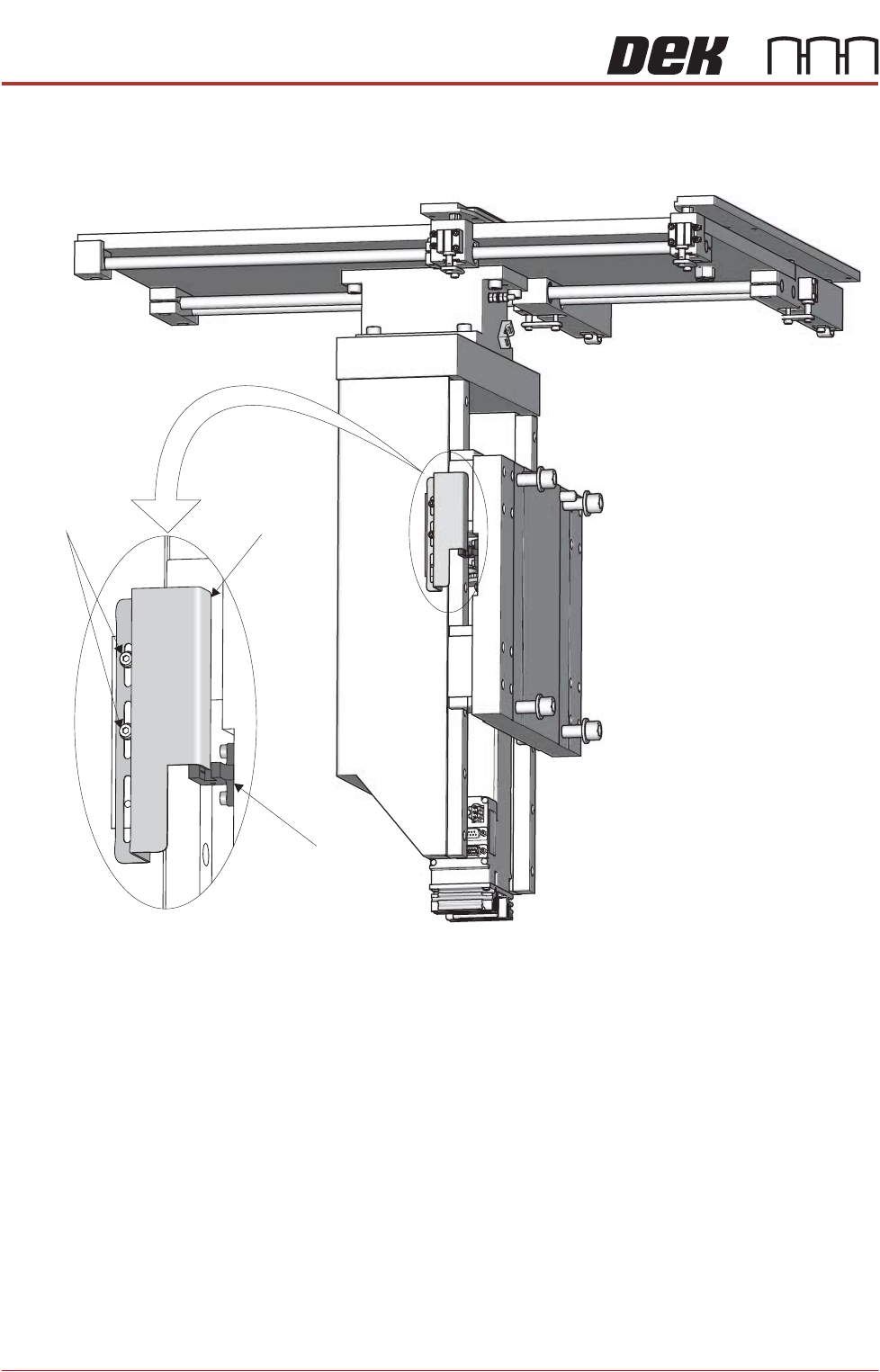
14. From the left hand side of the machine, slacken the two home vane securing
screws.
15. If the rising table needs to be higher, move the home vane downwards and
secure the two home vane securing screws.
16. If the rising table needs to be lower, move the home vane upwards and
secure the two home vane securing screws.
17. Remove the steel rule from the machine.
18. Remove the screen from the machine.
19. Close the front printhead cover.
20. Select Run Diagnost.
21. Repeat Steps 9 to 20.
22. Refit the safety cover.
23. Select Exit.
24. Select Exit.
25. Select Back.
Rising Table
Home Sensor
Rising Table
Home Vane
Vane Securing
Screws
TECHNICAL REFERENCE
ADJUSTMENTS AND SETTINGS
Chapter Issue 1, Apr 15 Reel to Reel Manual 1.9
Product Guides
and Transport
Clamps
The product guides on the inroad and the transport clamps on the outroad are
adjusted to within 0.5mm of the product reel, Setup - Product Changeover in the
User chapter of this manual refers.
Transport Carriage
Belts
The position of the transport carriage belts is dependent on the product width,
the belts need to support the outer edges and centre. More transport carriage
belts may be fitted if the product reel is very thin and requires more support.
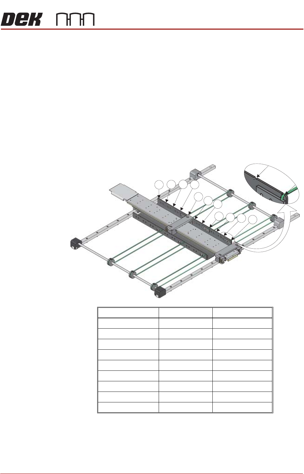
There are 11 possible positions for transport carriage belts, the front belt must
always remain in Position 1 to support the front of the product reel.
To reposition the transport carriage belts, use the following procedure:
1. Measure the width of the product reel.
2. Use the graphic and table below to determine the position for the rear and
centre transport carriage belts.
Product Reel Width Rear Belt Position Centre Belt Position
Greater than 440mm 11 5 or 6
398mm to 440mm 10 5
356mm to 397mm 9 4 or 5
314mm to 355mm 8 4
272mm to 313mm 7 3 or 4
230mm to 271mm 6 3
188mm to 229mm 5 2 or 3
146mm to 187mm 4 2
50mm to 145mm 3 2
7
8
9
10
11
4
5
6
1
2
3