192866 Issue 4 - Reel to Reel Manual LoRes.pdf - 第19页
TECHNICAL REFERENCE ADJUSTMENTS AND SETTINGS Chapter Issue 1, Apr 15 Reel to Reel Manual 1.9 Product Guides and T ransport Clamp s The product guides o n the inroad and the transport clamps on the outroad are adjusted to…
TECHNICAL REFERENCE
ADJUSTMENTS AND SETTINGS
1.8 Reel to Reel Manual Chapter Issue 1, Apr 15
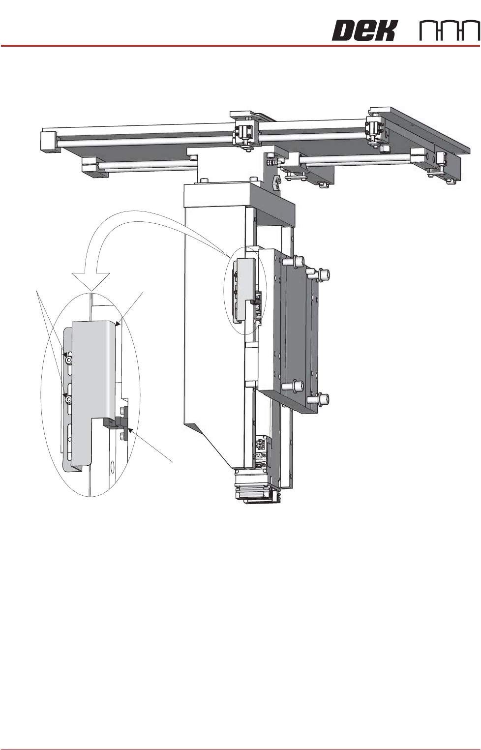
14. From the left hand side of the machine, slacken the two home vane securing
screws.
15. If the rising table needs to be higher, move the home vane downwards and
secure the two home vane securing screws.
16. If the rising table needs to be lower, move the home vane upwards and
secure the two home vane securing screws.
17. Remove the steel rule from the machine.
18. Remove the screen from the machine.
19. Close the front printhead cover.
20. Select Run Diagnost.
21. Repeat Steps 9 to 20.
22. Refit the safety cover.
23. Select Exit.
24. Select Exit.
25. Select Back.
Rising Table
Home Sensor
Rising Table
Home Vane
Vane Securing
Screws
TECHNICAL REFERENCE
ADJUSTMENTS AND SETTINGS
Chapter Issue 1, Apr 15 Reel to Reel Manual 1.9
Product Guides
and Transport
Clamps
The product guides on the inroad and the transport clamps on the outroad are
adjusted to within 0.5mm of the product reel, Setup - Product Changeover in the
User chapter of this manual refers.
Transport Carriage
Belts
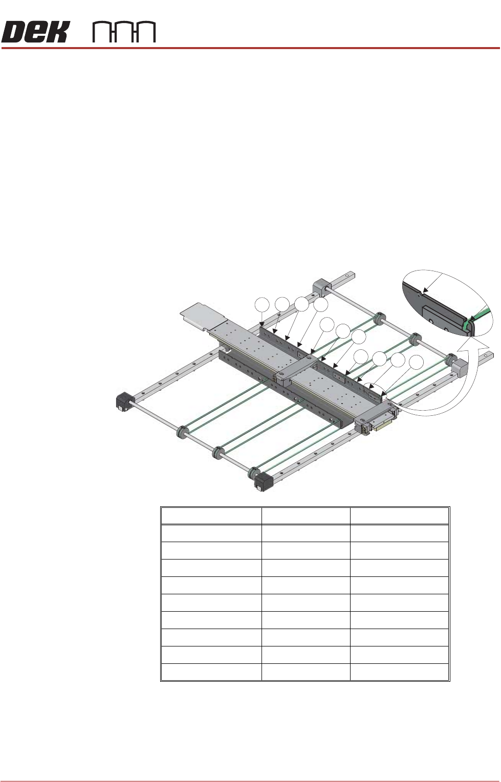
The position of the transport carriage belts is dependent on the product width,
the belts need to support the outer edges and centre. More transport carriage
belts may be fitted if the product reel is very thin and requires more support.
There are 11 possible positions for transport carriage belts, the front belt must
always remain in Position 1 to support the front of the product reel.
To reposition the transport carriage belts, use the following procedure:
1. Measure the width of the product reel.
2. Use the graphic and table below to determine the position for the rear and
centre transport carriage belts.
Product Reel Width Rear Belt Position Centre Belt Position
Greater than 440mm 11 5 or 6
398mm to 440mm 10 5
356mm to 397mm 9 4 or 5
314mm to 355mm 8 4
272mm to 313mm 7 3 or 4
230mm to 271mm 6 3
188mm to 229mm 5 2 or 3
146mm to 187mm 4 2
50mm to 145mm 3 2
7
8
9
10
11
4
5
6
1
2
3
TECHNICAL REFERENCE
ADJUSTMENTS AND SETTINGS
1.10 Reel to Reel Manual Chapter Issue 1, Apr 15
WARNING
BOARD CLAMPS. EXTREME CARE MUST BE EXERCISED WHEN WORKING IN
THE TOOLING AREA OF THE MACHINE TO AVOID INJURY. THE FOILS ON THE
FRONT AND REAR BOARD CLAMPS ARE VERY SHARP.
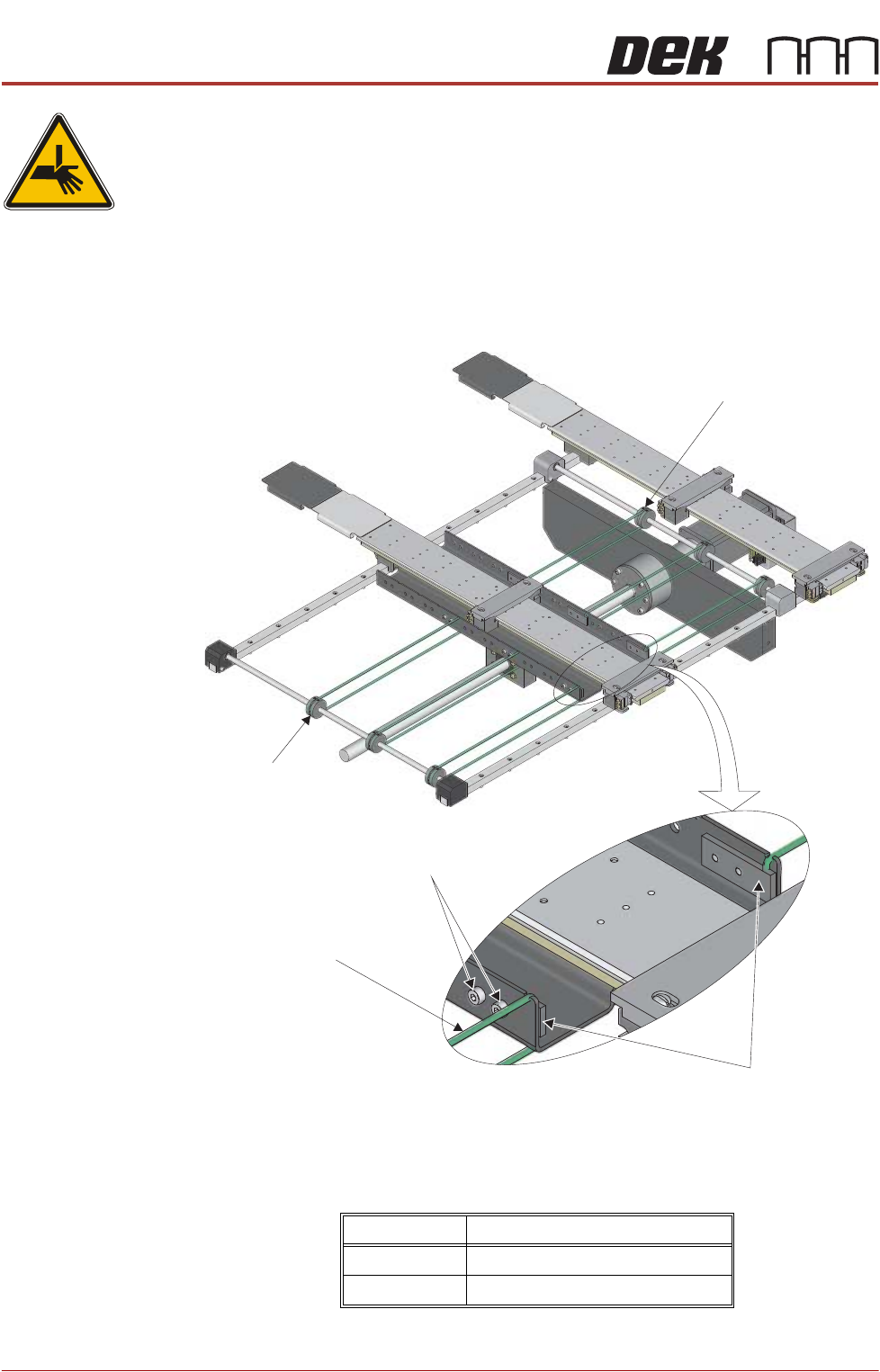
3. To move the position of a belt, slip the belt off the left and right belt pulleys.
4. Using a 3mm Allen key, remove the four belt clamp securing screws (two on
the right hand side of the inner transport vacuum plate and two on the left
hand side).
5. Fit the belt clamps to the new positions.
6. Fit the belt ends into the belt clamps ensuring the correct amount of belt is
protruding out of the bottom of the clamp, see table below:
7. Tighten the belt clamps.
Belt Position Dimension
Middle Belt 20mm below the clamp
Rear Belt 15mm below the clamp
Belt Clamps
Securing Screws
Transport Carriage Belt
Belt Pulley
(Left)
Belt Pulley
(Right)