TM6148.Force control options manual in YC8.pdf - 第18页
SMT Softw are Engineering Group IM Operations Y AMAHA MOTOR CO., L T D. 4. Calibration Position X (mm) X-coordinate where the calib r ation st ation is attached. * It is set when adjusting the ma c hine. 5. Calibration P…
SMT Software Engineering Group
IM Operations YAMAHA MOTOR CO., LTD.
Appendix
Machine setting
This section describes about parameters on machine setting to use Force Control.
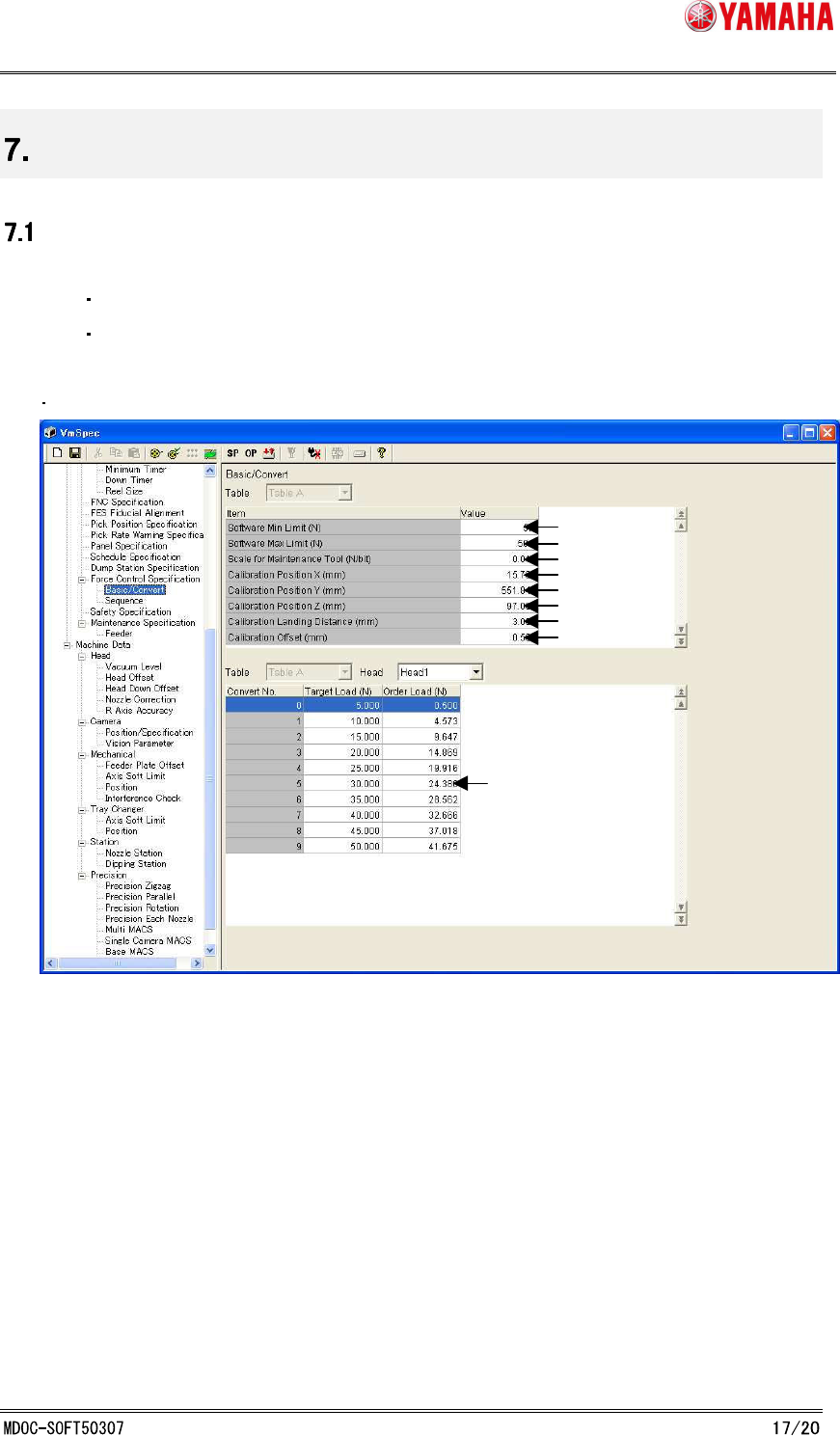
[Specification Information] - [Force Control Specification] - [Basic/Convert]
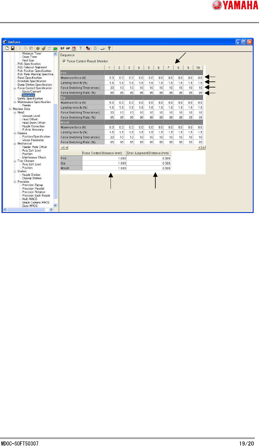
[Specification Information] - [Force Control Specification] - [Sequence]
[Specification Information] - [Force Control Specification] - [Basic/Convert]
1.Software Min Limit (N)
The minimum force value that can be set in parts data.
2. Software Max Limit (N)
The maximum load value that can be set in parts data.
3. Scale for Maintenance Tool (N/bit)
It is a gain on AD value of the calibration station.
Defined force value(N) per 1Bit.
* The calibration station is set when adjusting the machine.
1.
2.
3.
4.
5.
6.
7.
8.
9.
SMT Software Engineering Group
IM Operations YAMAHA MOTOR CO., LTD.
4. Calibration Position X (mm)
X-coordinate where the calibration station is attached.
* It is set when adjusting the machine.
5. Calibration Position Y (mm)
Y-coordinate where the calibration station is attached.
* It is set when adjusting the machine.
6. Calibration Position Z (mm)
Z-coordinate where the calibration station is attached.
* It is set when adjusting the machine.
7. Calibration Landing Distance (mm)
When a correction table is created on [CalibSm] - [084 LoadControl], Force Control
starts at the height calculated by subtracting this value from "Calibration Station
coordinate Z (mm)".
8. Calibration Offset (mm)
When a correction table is created on [CalibSm] - [084 LoadControl], Force Control
starts at the height calculated by subtracting this value from "Calibration Station
coordinate Z (mm)".
9. Correction Table
It is created on [CalibSm] - [084 LoadControl].
Target load and the measuring force table when outputting the load.
* It is set when adjusting the machine.
[Specification Information]-[Force Control Specification]-[Sequence]
SMT Software Engineering Group
IM Operations YAMAHA MOTOR CO., LTD.
10. Sequence Table
10 different patterns can be set for each operation Pick / Dip / Mount.
11. Maximum force (N)
Operation sequence to the force value set on parts data is decided by this value
* Please do not change this setting value.
12. Landing velocity (%)
It is a velocity to contact parts to a board.
* Please do not change this setting value.
13. Force Switching Time (msec)
Time to switch from “impact value suppression current” to “thrust control current”.
* Please do not change this setting value.
14. Force Switching Rate (%)
100 * (impact value suppression current) / (thrust control current).
* Please do not change this setting value.
15. Force Control Distance (mm)
During auto-running, Force Control starts from the height calculated by subtracting this
value from the target position.
16. Error Judgment Distance (mm)
This is the distance to judge as insertion error. During auto-running, it judges as error,
11.
12.
13.
15.
16.
10.
14.