TM6148.Force control options manual in YC8.pdf - 第6页
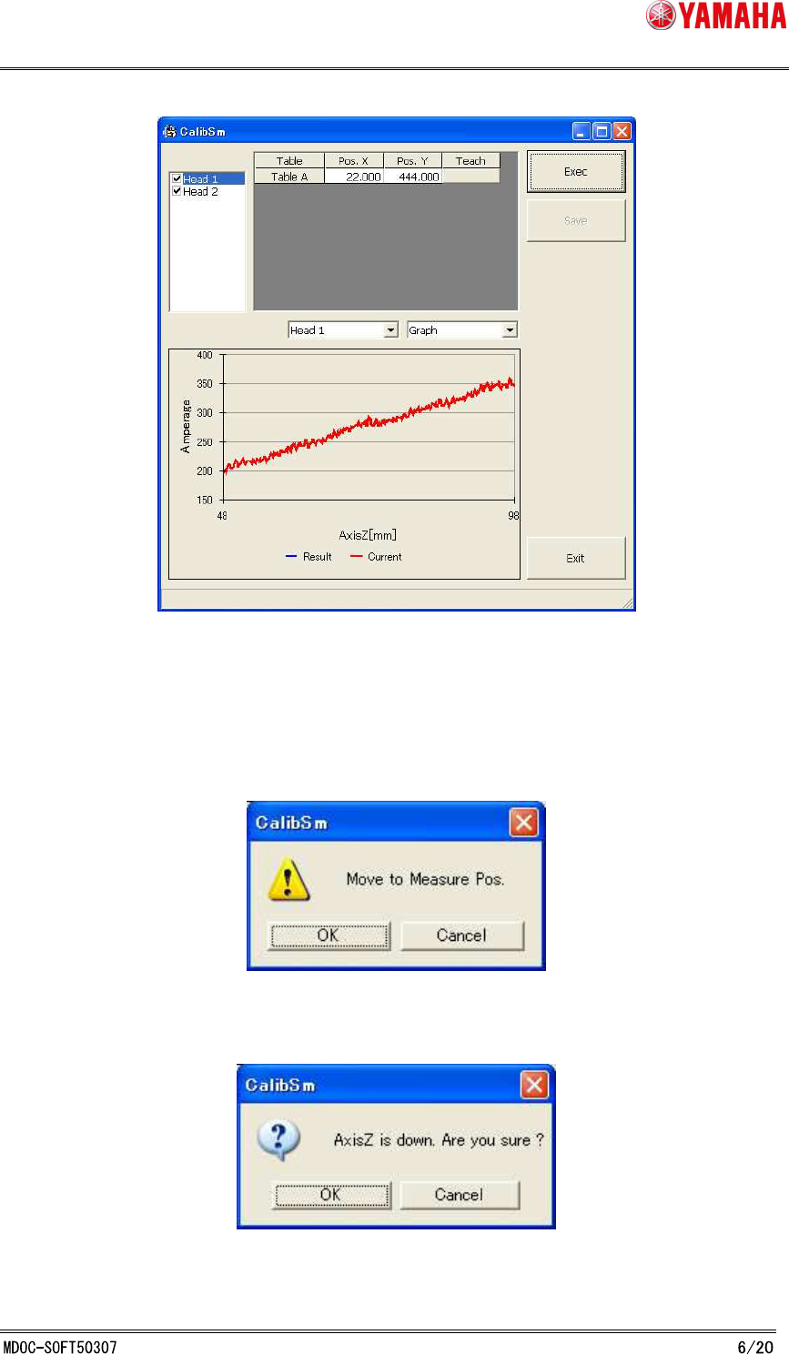
SMT Softw are Engineering Group IM Operations Y AMAHA MOTOR CO., L T D. Fig. 3.3.3.1 Height Offset Force Correction Adjustment Procedure: 1. Select a head from the list on the upper lef t of the screen. 2. Click the [Exe…
SMT Software Engineering Group
IM Operations YAMAHA MOTOR CO., LTD.
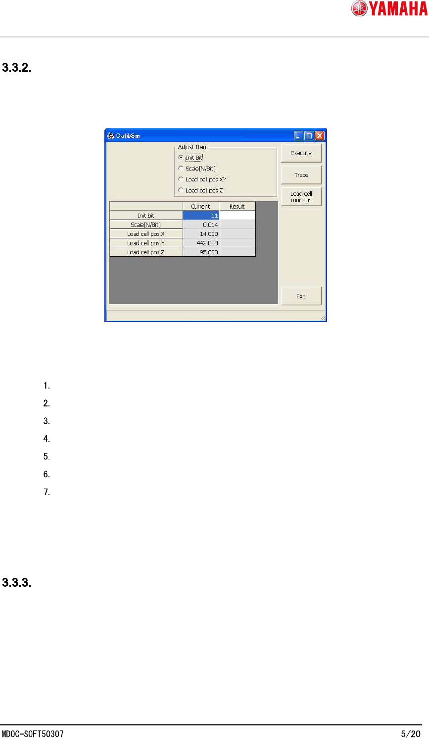
Force Control Correction Station Adjustment
On the [CalibSm] - [083 LoadCell Pos.] dialog, adjust XYZ-coordinates and initial bit of the load
cell. (See Fig. 3.3.2.1)
Fig. 3.3.2.1 Force Control Correction Station Adjustment
Procedure:
Select “Initial Bit” with nothing on the load cell, and click the [Execute] button.
Press the [Load cell monitor] button to make sure that N-value is 0± 0.1.
Select "Load cell pos.XY".
Press the [Execute] button, and the fiducial camera teaches the load cell position.
Select "Load cell pos.Z".
Set nozzle- 63 to Head 1.
Press the [Execute] button.
* “Scale[N/Bit]” of the load cell is already adjusted in advance.
Height Offset Force Correction Adjustment
On the [Utilities] - [099 Load Ect. Offset Adjust] dialog, adjust the offset position of Z-axis for
each head. (See Fig. 3.3.3.1)
SMT Software Engineering Group
IM Operations YAMAHA MOTOR CO., LTD.
Fig. 3.3.3.1 Height Offset Force Correction Adjustment
Procedure:
1. Select a head from the list on the upper left of the screen.
2. Click the [Exec] button, then following message is displayed.
Select [OK], and XY-axis moves to the measurement position.
Then the following message is displayed.
Select [OK], and measurement starts.
SMT Software Engineering Group
IM Operations YAMAHA MOTOR CO., LTD.
* Measurement position is originally set on the dumping position. If you want to
change the position, click the [Cancel] button, and change the value of [Pos.X] and
[Pos.Y], or move the axis by hand, then click the [Teach] button.
3. When measurement is completed, adjustment value is displayed.
The [Graph] tab indicates adjusted value in blue, and current value is in red.
The [Number] tab indicates each value of the selected head.
4. Click the [Save] button, and the following message is displayed.
To implement this adjustment value, select "Yes".
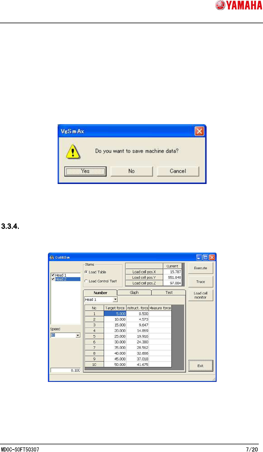
Force Control Correction Table Adjustment
On the [Utilities] - [084 LoadControl] dialog (Fig. 3.3.4.1), create a correction table of the target
force and the measuring force at the time of the output force of each head.
Fig. 3.3.4.1 Force Control Correction Table Adjustment
Procedure:
1. Select a head from the list on the upper left of the screen, then click the [Exec]