TM6148.Force control options manual in YC8.pdf - 第4页
SMT Softw are Engineering Group IM Operations Y AMAHA MOTOR CO., L T D. Hardware s etting and adjustment for F orce Control T o use Force Control, make adjustment and setting as shown below . Force Calibration S tation F…
SMT Software Engineering Group
IM Operations YAMAHA MOTOR CO., LTD.
Setting and adjustment method
Force Control Setting (Machine Setting)
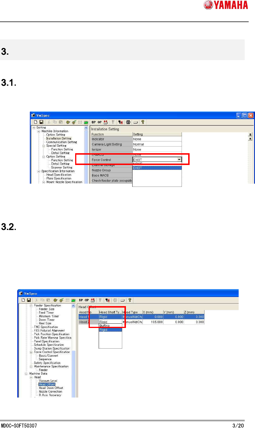
To use this function, set [Machine] - [Machine Information] - [Installation setting] - [Option] -
[Force Control] to “EXIST”. (See Fig. 3.1.1)
Fig. 3.1 Force Control Setting
Head Type Setting (Machine Setting)
This function works only with rigid type heads.
After attaching rigid type heads on machine, set [Machine] - [Machine Data] - [Head] - [Head
Offset] - [Head Shaft Type] to “Rigid”. (See Fig. 3.2.1)
[Head Shaft Type] can be selected separately for each head, but with this function, all of the
heads must be the same in this setting.
Fig. 3.2.1 Head Type Setting
SMT Software Engineering Group
IM Operations YAMAHA MOTOR CO., LTD.
Hardware setting and adjustment for Force Control
To use Force Control, make adjustment and setting as shown below.
Force Calibration Station
Force Control setting is adjusted here.
Force Calibration Station Adjustment
XYZ-coordinate and initial bit of the load cell, which is permanently attached to the force
calibration station.
Height Offset Force Correction Adjustment
In the Force Control function, the current value is changed according to the position of Z-axis,
so that it is necessary to adjust the offset value.
Force Control Correction Table Adjustment
In the Force Control function, there is a difference between the desired force value and the
control force value when outputting the force, so that it is necessary to create a correction
table.
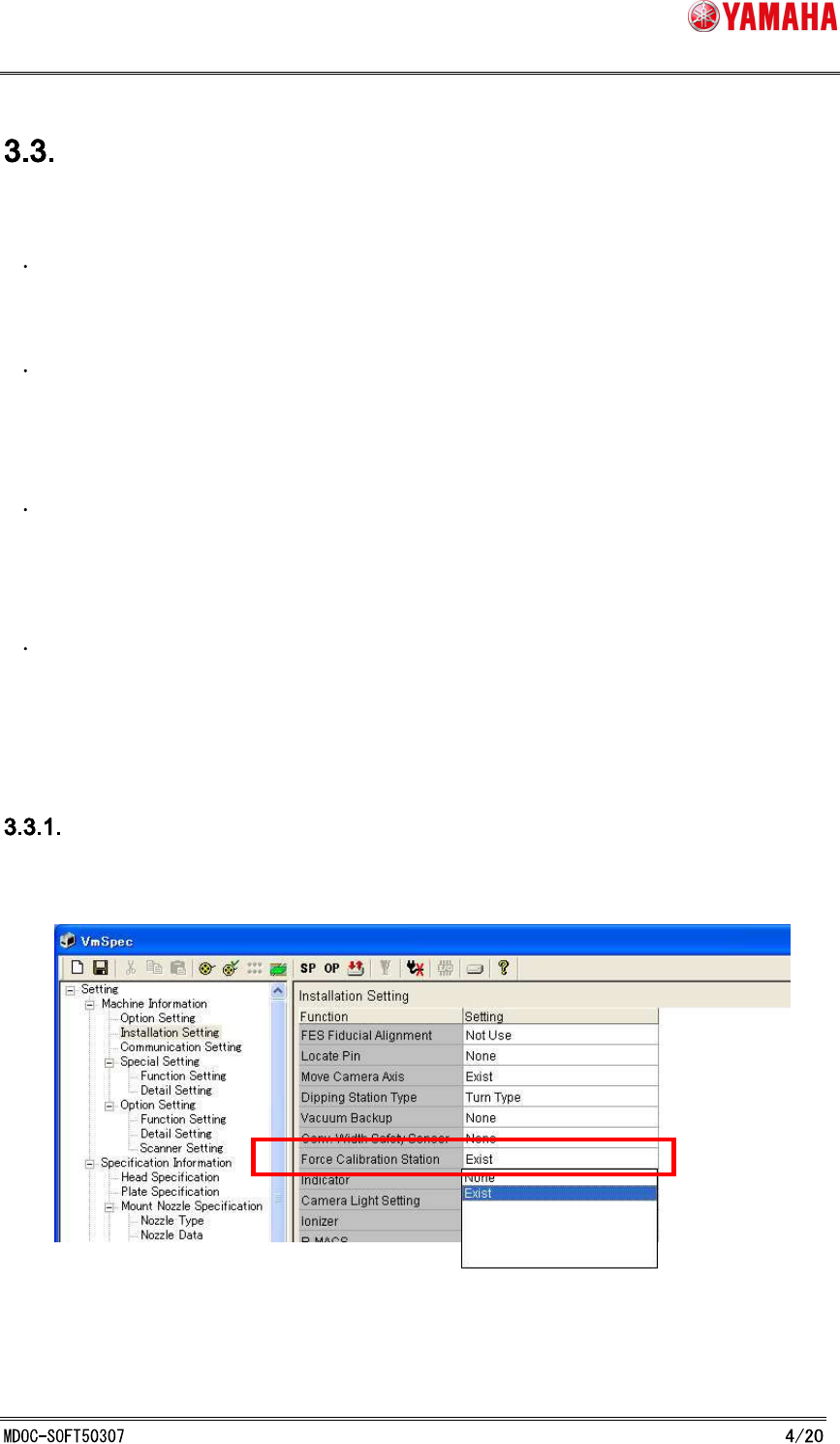
Force Calibration Station Setting
Set [Machine] - [Machine Information] - [Installation setting] - [Option] - [Force Calibration
Station] to “EXIST”. (See Fig. 3.3.1.1)
Fig. 3.3.1.1 Force Calibration Station Setting
SMT Software Engineering Group
IM Operations YAMAHA MOTOR CO., LTD.
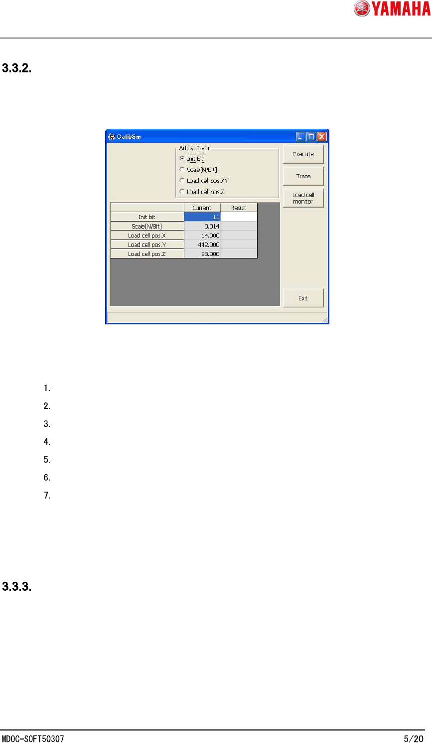
Force Control Correction Station Adjustment
On the [CalibSm] - [083 LoadCell Pos.] dialog, adjust XYZ-coordinates and initial bit of the load
cell. (See Fig. 3.3.2.1)
Fig. 3.3.2.1 Force Control Correction Station Adjustment
Procedure:
Select “Initial Bit” with nothing on the load cell, and click the [Execute] button.
Press the [Load cell monitor] button to make sure that N-value is 0± 0.1.
Select "Load cell pos.XY".
Press the [Execute] button, and the fiducial camera teaches the load cell position.
Select "Load cell pos.Z".
Set nozzle- 63 to Head 1.
Press the [Execute] button.
* “Scale[N/Bit]” of the load cell is already adjusted in advance.
Height Offset Force Correction Adjustment
On the [Utilities] - [099 Load Ect. Offset Adjust] dialog, adjust the offset position of Z-axis for
each head. (See Fig. 3.3.3.1)