DT_ELMC-V3-EN_REV-B.1_L.pdf - 第12页
ELECTROVA P ® E LMC 12 3.3 DISPERSI ON TUBE POSITIONING Steam disper sion tubes: The steam from the humidi fier is injected in a duct or an air handling unit via a steam dispersi on tube. To obtain the best perfo rmance …
ELECTROVAP® ELMC
11
3.2 WATER SUPPLY
3.2.1 Recommendation
Our device is designed to be used with any following water type:
✓ drinking water (according to Directive 98/83/EEC, TH
(French grade) between 0°fH and 40°fH and conductivity
between 250 µS/cm and 1000 μS/cm)
✓ softened water,
✓ demineralized water, reverse osmosis water: use
possible under conditions. Please contact our services
The demineralized water is corrosive; use appropriate piping material: stainless steel, PVC.
Softened water: Its use is not necessary, but possible. TH should be between 0° fH and 2° fH.
Water analysis is recommended to determine the level of sodium chloride.
Do not hesitate to contact our services for support.
3.2.2 Recommendations on connection
Network water pressure: The pressure must be stable and between 2 bar and 8 bar MAX. in case the water pressure
exceeds 8 bar, a water regulator calve must be used.
Network water temperature: < 40 °C.
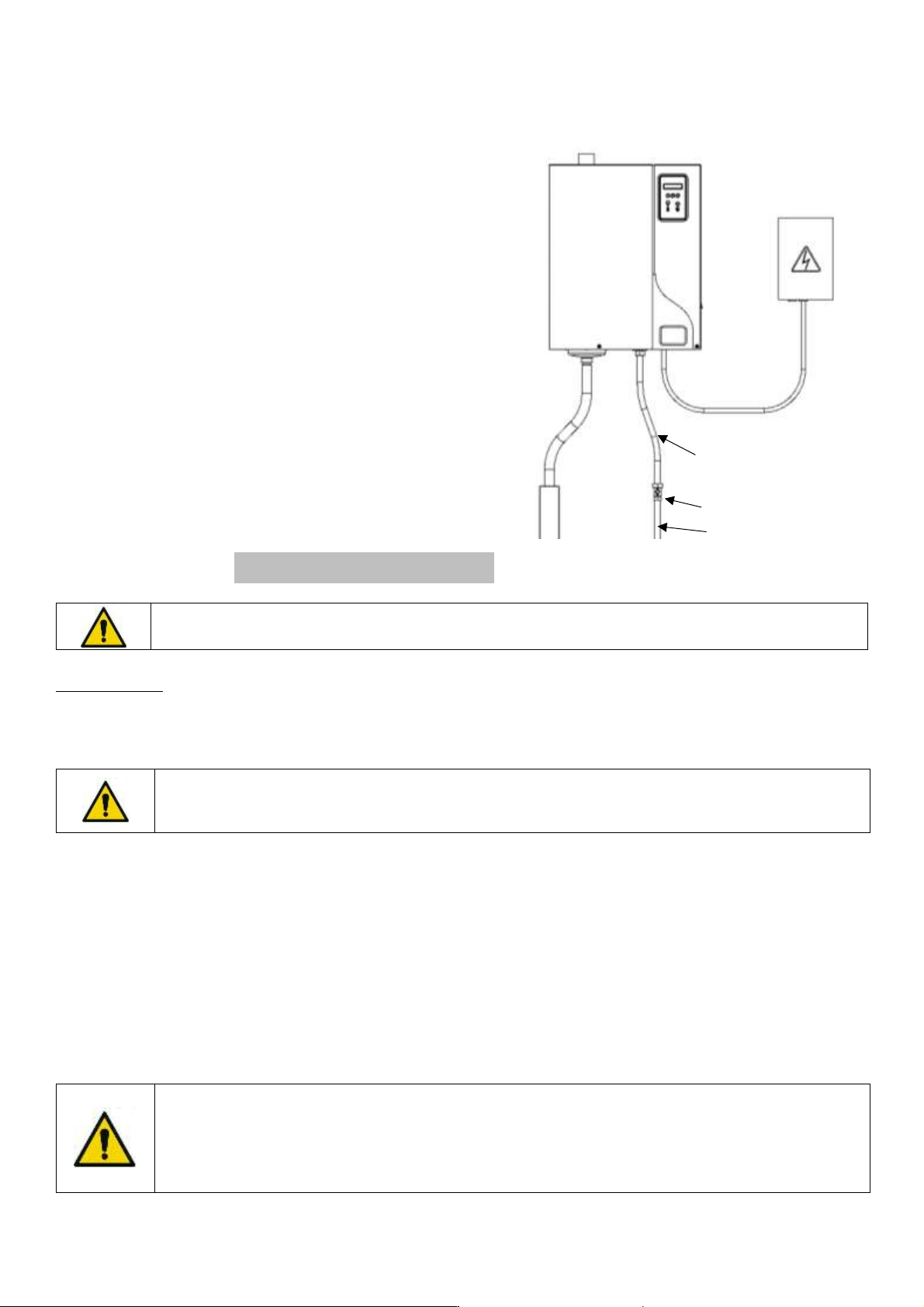
Please note that the water supply is connected at the lower part of the unit.
For easy maintenance, the water inlet valve is equipped with a filter strainer which should be checked periodically. It
is essential to install an isolation valve near the humidifier to facilitate maintenance.
OVERFLOW RISKS: it is recommended to install a collecting water tank under the humidifiers to
prevent overflow. This is essential if the unit is installed in false ceilings or above important rooms
(example: museum room, showroom, laboratory etc.). Make sure the container is connected to the
wastewater system.
An excess of sodium chloride may generate foam which disturbs the correct running of the humidifier.
It is mandatory to use a duplex softener.
Max. chloride content: 80 mg/l
Isolation valve
Water system
Fig. 3-2. Humidifier water supply
Flexible braided hose
with 3/4” FF thread
ELECTROVAP® ELMC
12
3.3 DISPERSION TUBE POSITIONING
Steam dispersion tubes:
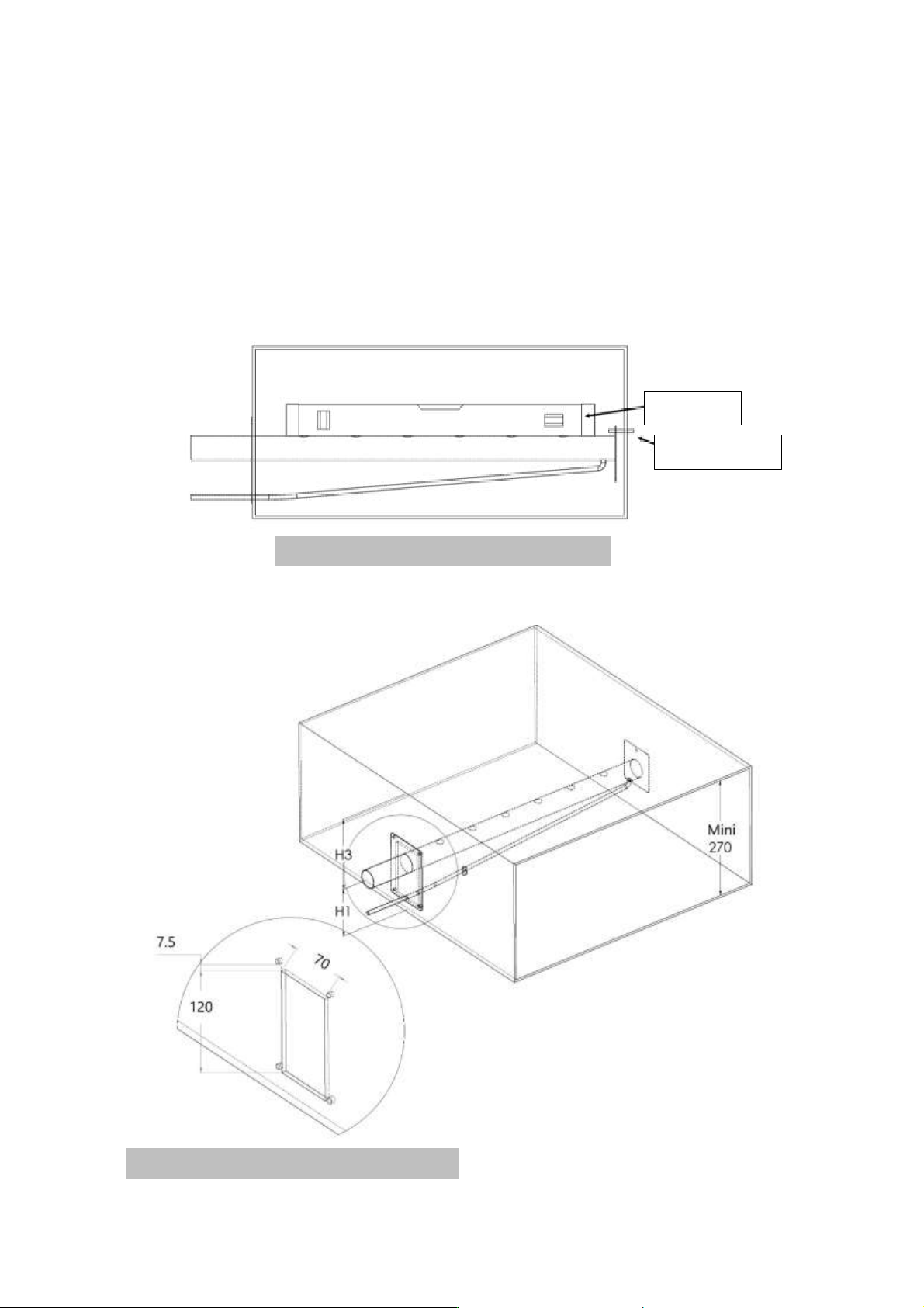
The steam from the humidifier is injected in a duct or an air handling unit via a steam dispersion tube. To obtain the
best performance of the humidifier, select the longest pipe.
Fig. A 3-3. Steam dispersion tubes positioning
Spirit level
Threaded rod
Fig. B 3-3. Hole dimension to be cut in the duct
ELECTROVAP® ELMC
13
3.3.1 Absorption distance "D"
Make sure that the absorption distance is met in order to let the air absorb the steam dispersed by the tubes. In this
absorption distance, the steam is still visible in the air stream in the form of fog. If any furniture is placed in this area,
condensate may occur. For this reason, it is imperative to consider this absorption distance when placing the
humidifiers.
3.3.2 How to calculate absorption distance « D »
In order to determine the absorption distance, the attached calculation table can be used:
▪ RH1 = relative humidity of air before humidification in %.
▪ RH2 = relative humidity of air after humidification in %.
▪ D mini = minimum absorption distance in meters (m).
Inlet RH1 [%]
5
10
20
30
40
50
60
70
Outlet RH2 [%]
Minimum absorption distance "D" [m]
40
0,9
0,8
0,7
0,5
-
-
-
-
50
1,1
1
0,9
0,8
0,5
-
-
-
60
1,4
1,3
1,2
1
0,8
0,5
-
-
70
1,8
1,7
1,5
1,4
1,2
1
0,7
-
80
2,3
2,2
2,1
1,9
1,7
1,5
1,2
0,8
90
3,5
3,4
3,2
2,9
2,7
2,4
2,1
1,7
This calculation table is to be used for temperatures between 20°C and 25°C (68°F to 77°F) (Maximum air speed 5m/s).
For calculated distances, contact your Devatec agent.
3.3.3 Minimum absorption distance
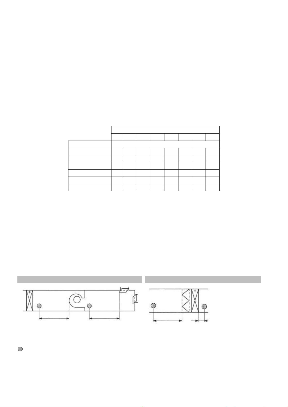
The steam dispersion pipes must be positioned after the minimum specified absorption distance. Please follow the
guidelines depending on the configuration of your air handling unit.
Fig. B 3-3. Before/after a fan
Fig. C 3-3. Before/after heating battery or filter
1.5 x D before a particle filter or absolute filter
= Dispersion tube
D
D
1.5 x D
5 cm