DT_ELMC-V3-EN_REV-B.1_L.pdf - 第13页
ELECTROVA P ® E LMC 13 3.3 .1 Absorption distance "D" Make sure that the absorption di stanc e is m et in order to l et the air absorb t he steam dispersed by the tubes. I n this absorption di stanc e, the stea…
ELECTROVAP® ELMC
12
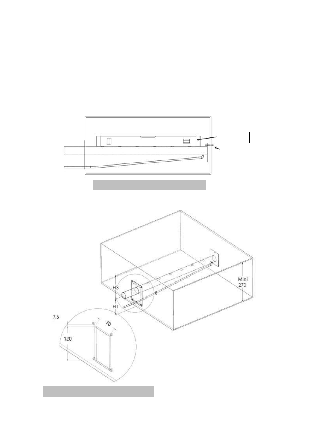
3.3 DISPERSION TUBE POSITIONING
Steam dispersion tubes:
The steam from the humidifier is injected in a duct or an air handling unit via a steam dispersion tube. To obtain the
best performance of the humidifier, select the longest pipe.
Fig. A 3-3. Steam dispersion tubes positioning
Spirit level
Threaded rod
Fig. B 3-3. Hole dimension to be cut in the duct
ELECTROVAP® ELMC
13
3.3.1 Absorption distance "D"
Make sure that the absorption distance is met in order to let the air absorb the steam dispersed by the tubes. In this
absorption distance, the steam is still visible in the air stream in the form of fog. If any furniture is placed in this area,
condensate may occur. For this reason, it is imperative to consider this absorption distance when placing the
humidifiers.
3.3.2 How to calculate absorption distance « D »
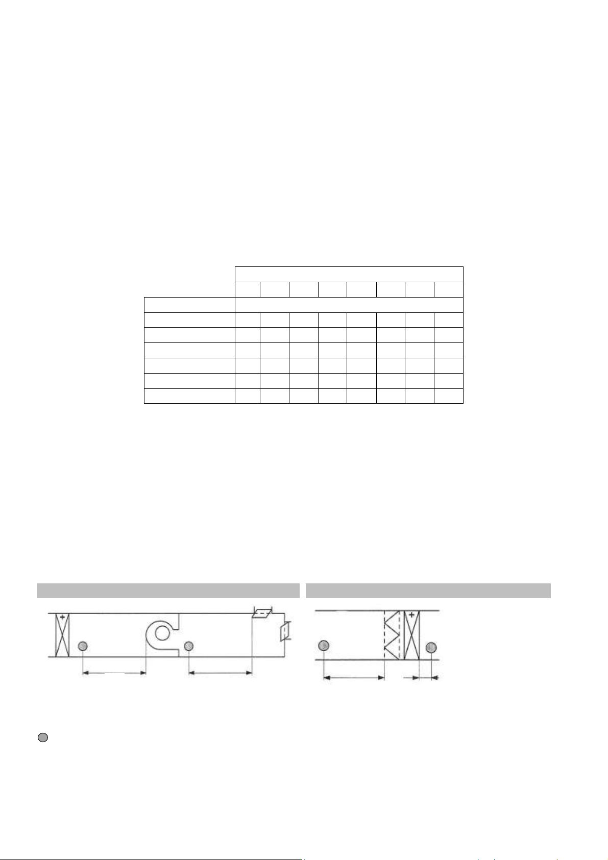
In order to determine the absorption distance, the attached calculation table can be used:
▪ RH1 = relative humidity of air before humidification in %.
▪ RH2 = relative humidity of air after humidification in %.
▪ D mini = minimum absorption distance in meters (m).
Inlet RH1 [%]
5
10
20
30
40
50
60
70
Outlet RH2 [%]
Minimum absorption distance "D" [m]
40
0,9
0,8
0,7
0,5
-
-
-
-
50
1,1
1
0,9
0,8
0,5
-
-
-
60
1,4
1,3
1,2
1
0,8
0,5
-
-
70
1,8
1,7
1,5
1,4
1,2
1
0,7
-
80
2,3
2,2
2,1
1,9
1,7
1,5
1,2
0,8
90
3,5
3,4
3,2
2,9
2,7
2,4
2,1
1,7
This calculation table is to be used for temperatures between 20°C and 25°C (68°F to 77°F) (Maximum air speed 5m/s).
For calculated distances, contact your Devatec agent.
3.3.3 Minimum absorption distance
The steam dispersion pipes must be positioned after the minimum specified absorption distance. Please follow the
guidelines depending on the configuration of your air handling unit.
Fig. B 3-3. Before/after a fan
Fig. C 3-3. Before/after heating battery or filter
1.5 x D before a particle filter or absolute filter
= Dispersion tube
D
D
1.5 x D
5 cm
ELECTROVAP® ELMC
14
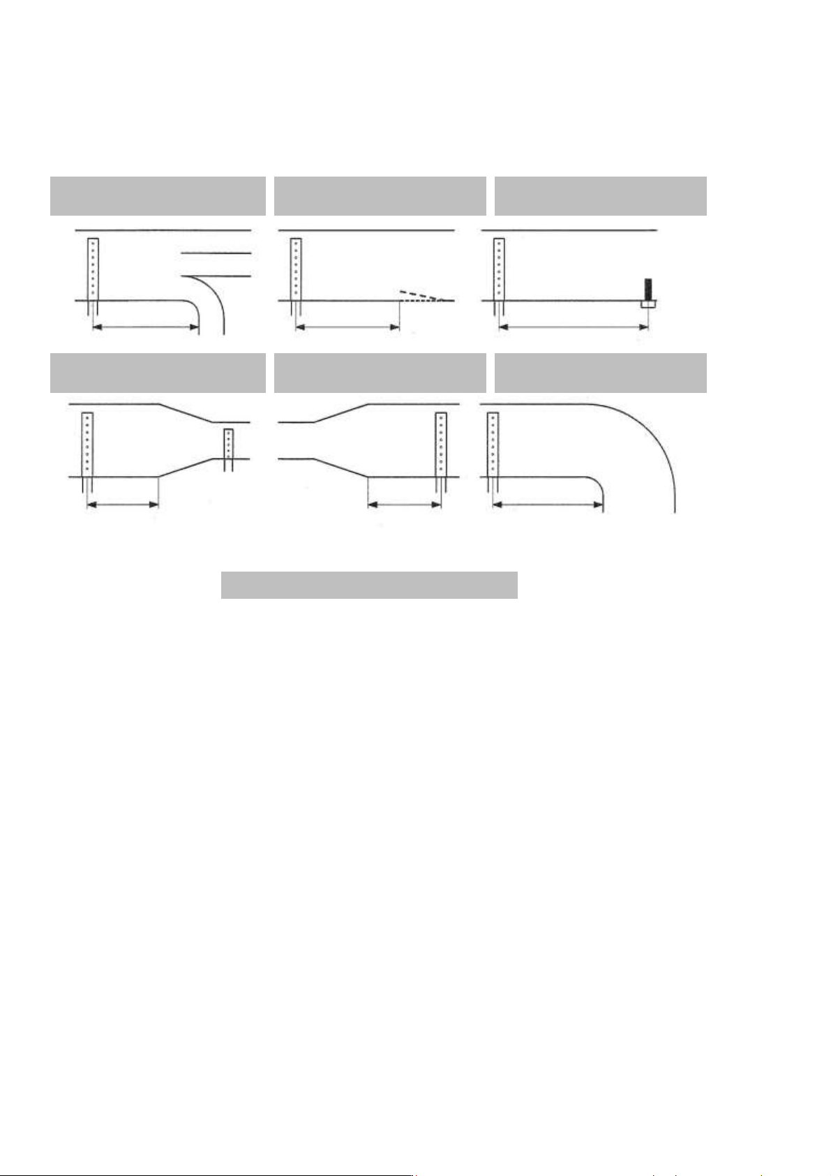
3.3.4 Minimum installation distances
• A high limit humidistat must be installed in the duct to stop the humidifier in case the level of humidity exceeds
the preset value.
• If the recommended distances cannot be met, please contact Devatec or their authorized agent for an alternative
solution.
• Make sure the distances are met, if this is not possible, please contact your Devatec agent.
1) Before a junction
2) Before an air grid
3) Before a humidity
sensor
4) Before/after
strangulation
5) Before enlargement
6) Before a bend
Fig. D 3-3. Installation distances
D
D
5 x D
0.5 x D
0.5 x D
D