DT_ELMC-V3-EN_REV-B.1_L.pdf - 第18页
ELECTROVA P ® E LMC 18 3.5 CONDENSATE DRAINING WITH SIPH O N The c ondensate ho se must not be directly connec ted to the pu blic sewerage network. H min. (mm) = P (Pa)/10 with P = ab solute pressure of th e air han dlin…
ELECTROVAP® ELMC
17
3.4 STEAM OUTLET
1. Preferably use a flexible steam hose that is resistant to a temperature of 100°C.
NB: when new hoses are installed, a smell of burnt plastic may be smelt during the first running of the steam
humidifier. This is normal and will eventually diminish.
2. Steam hose selection:
Model
ELMC
5 to 15
ELMC
20 to 30
ELMC
40 to 60
ELMC
90
Number of steam outputs
1
1
2
3
Diameter steam output hose [mm]
Ø 25-40
Ø 40 or 25
Ø 40 or 25
Ø 40 or 25
3. ELMC humidifiers can operate with a pressure (P) higher than the atmospheric pressure in the ducts, but under
the following conditions:
• If P is less than 150 mm WC or 1470 Pa.
• If P is greater than 150 mm WC (1470 Pa), options are available up to 700 mm WC (6860 Pa).
4. For the installation of the steam hose, depending on your environment, please respect the recommendations
below and use the appropriate tangential hose clamps.
• Flexible steam hose length 3 m max.
• Stainless steel or copper pipe with a slightly larger diameter, grounded. Use a flexible steam hose cuff to connect
the humidifier to the steam distribution pipe. The length of the pipe must be thermally insulated and should not
exceed 6 m.
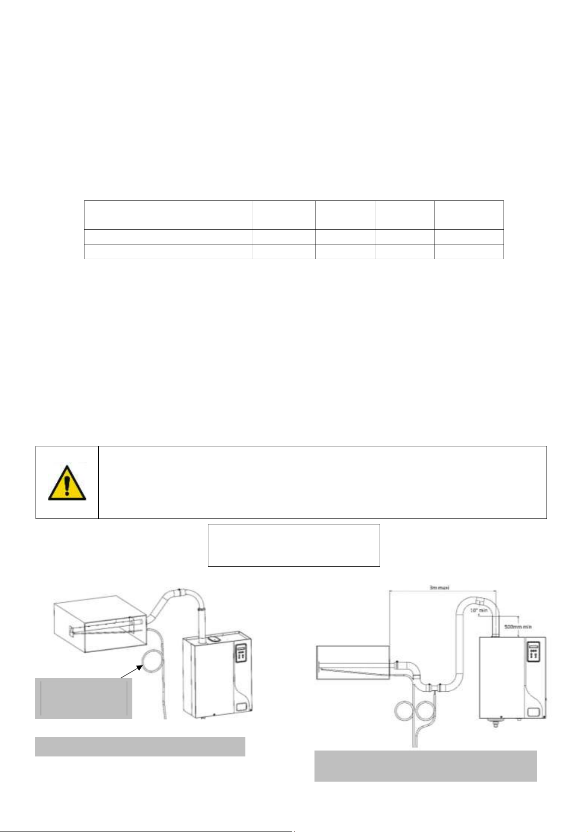
Always have a slope in the same direction (up or down); the steam hose must be free of
kinks and sags to allow for gravity drainage of condensate.
Make sure that the steam hose is not leaky. Failure to follow these instructions can lead
to serious malfunctions.
Radius of the diameter steam pipe:
• Ø 25 – 250 mm minimum
• Ø 40 – 400 mm minimum
Fig. B 3-4. Additional drip leg when steam distribution
below humidifier
Ø 300 mm min./
12’’ min.
Fig. A 3-4. Standard installation
ELECTROVAP® ELMC
18
3.5 CONDENSATE DRAINING WITH SIPHON
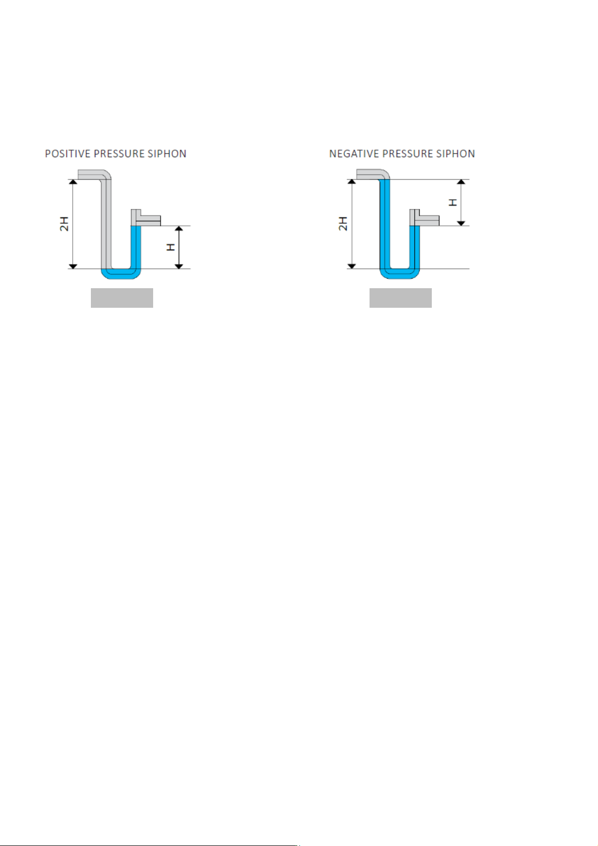
The condensate hose must not be directly connected to the public sewerage network.
H min. (mm) = P (Pa)/10
with P = absolute pressure of the air handling unit or the ventilation duct
Fig. A 3-5.
Fig. B 3-5.
ELECTROVAP® ELMC
19
3.6 DRAIN HOSE CONNECTION
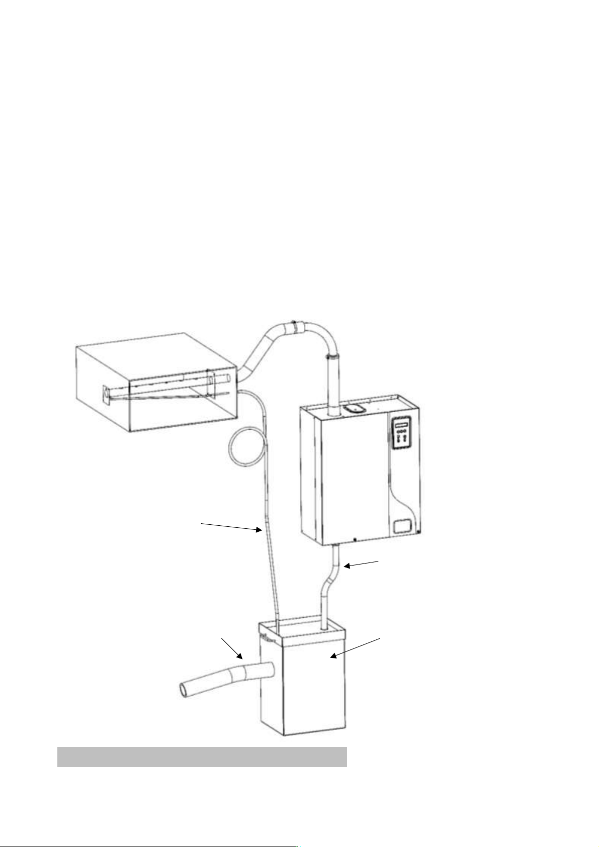
The following drawing shows the drain hose connection that should be made.
Use a Ø 25 mm rubber drain hose with the 2 supplied hose clamps, heat-resistant (up to 100°C).
Connect the hose to the draining system. Regular replacement is recommended.
If rigid piping is used, it must be a heat-resistant PVC material (up to 100 °C).
The discharge hose must be free from any obstacle.
It is recommended that each humidifier has its own drain pipe.
If possible, use a collecting water tank with a lid (see the picture below).
Drain hose (optional)
Collecting water tank
(optional)
Condensate hose (optional)
Pipe - minimum Ø 60mm (optional)
Fig. A 3-6. Example of Installation