DT_ELMC-V3-EN_REV-B.1_L.pdf - 第50页
ELECTROVA P ® E LMC 50 6.3 DRAIN VALVE The drain valve should be maintained whenever t he steam tank is maintained or ch anged. • Onc e the tank is out o f the humidifier, disconn ect t he drai n valve supp ly c ables (I…
ELECTROVAP® ELMC
49
CYLINDER REPLACEMENT METHOD
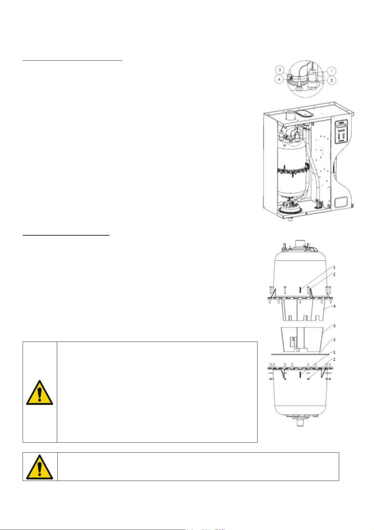
• Drain the cylinder by pressing the drain button and wait until the cylinder is
completely empty. The message "DRAINING CYCLE OVER" appears.
• Turn off power of the power circuits (in the general electrical cabinet) and
control system located on the front of the device.
• Remove the door from the hydraulic compartment, remove the power cable
connectors and water level sensor (1 and 2). Then loosen the clamp to
disconnect the steam outlet hose (3 and 4).
• WARNING! Risk of burns. If the drain is recent, the steam cylinder is still
burning. Therefore, wait for it to cool down.
• Lift the cylinder up by pressing down on its base to release it from the foot of
the drain valve.
• Remove the top of the cylinder from the retaining clip and remove it from the
hydraulic compartment.
• Please tighten the steam hose slightly on the cylinder, only when the cylinder
is cold, to avoid deformation.
CYLINDER CLEANING METHOD
• After removing the cylinder, mark the two half-cylinders (1) at once.
• Remove the nuts and screws holding with two keys of 8 (2), open the cylinder.
Remove the strainer and seal, then clean them (3).
• Clean the electrodes, the brace, and the inside of the cylinder's bodies by
scraping the limestone (it is possible to use passed acid for power electrodes) (4).
• Rinse the electrodes, the bodies of the cylinder, the brace. Do not forget to clean
the strainer in the cylinder foot.
WARNING! Never shake the edge of the cylinder shells to remove
limescale. It is imperative to systematically replace the cylinder seal
and reposition it in its housing. Always replace the sealing ring and
insert it into the profile of the lower barrel of the cylinder. Then insert
the upper part (electrodes).
Make sure to align the two shells, reposition the nuts and screws.
Tighten by screwing the screws opposite each other so that the seal
is not deformed.
If the power cables change, be sure to run them through the humidifier according to the wiring
diagram explained previously.
ELECTROVAP® ELMC
50
6.3 DRAIN VALVE
The drain valve should be maintained whenever the steam tank is maintained or changed.
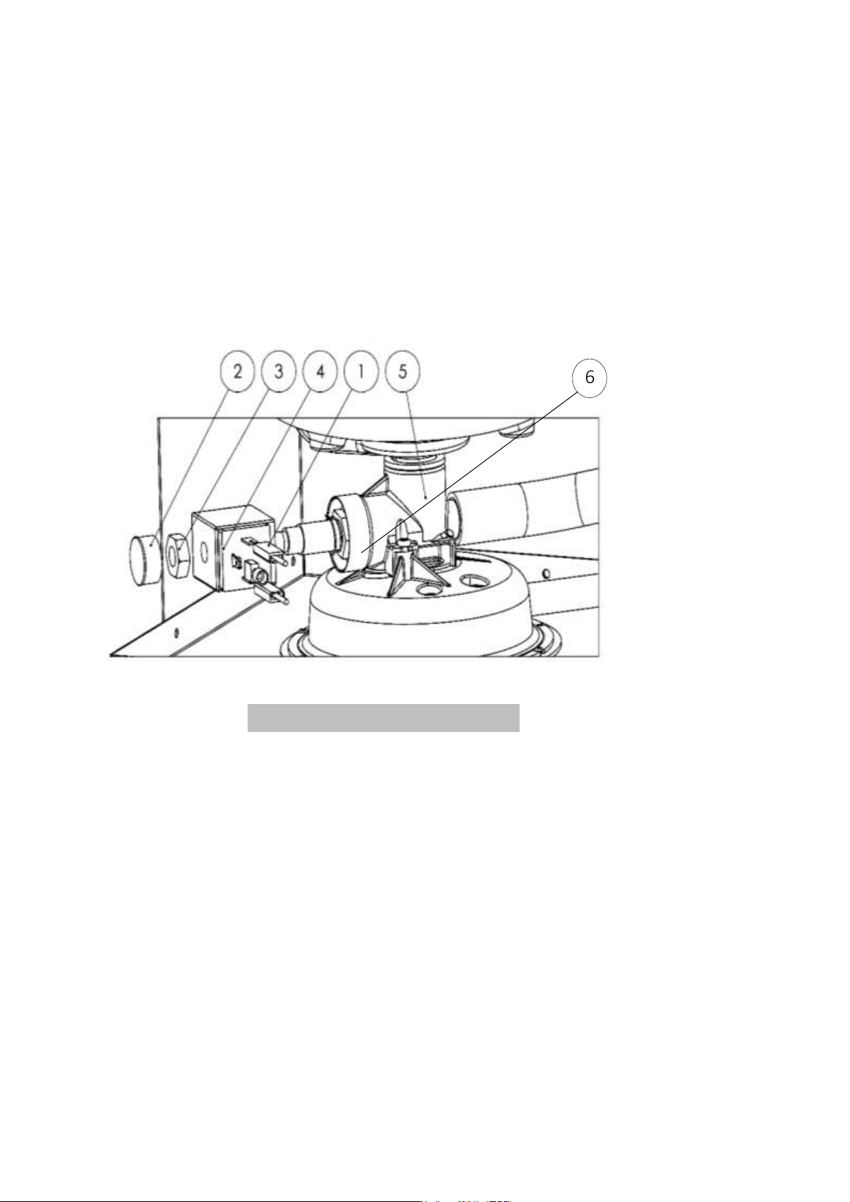
• Once the tank is out of the humidifier, disconnect the drain valve supply cables (Item 1).
• Unscrew the nut and the plastic protection of the supply coil (Item 2 & 3).
• Now you can remove the coil (Item 4) from the valve body (Item 5).
• Use a pair of pliers or a 19" wrench to unscrew the valve plug (Item 6) from the valve body (Item 5).
• Check and clean, if necessary, the inside of the valve body by running water through the hole.
Reassemble the drain valve as original, before repositioning the tank, by proceeding as follows:
1. Position the tank bottom in the valve connection, push down.
2. Replace the steam hose and do not forget to tighten the hose clamp.
Ensure that all the clamps are properly tightened whenever the humidifier is maintained.
6
Fig. 6-3. Humidifier drain valve
ELECTROVAP® ELMC
51
6.4 WATER INLET VALVE
Maintenance of the water inlet valve is to be done after the first 50
hours of operation. Thereafter, twice a year (minimum).
• Switch the appliance off.
• Switch off the water supply to the humidifier and unscrew the
water supply hose.
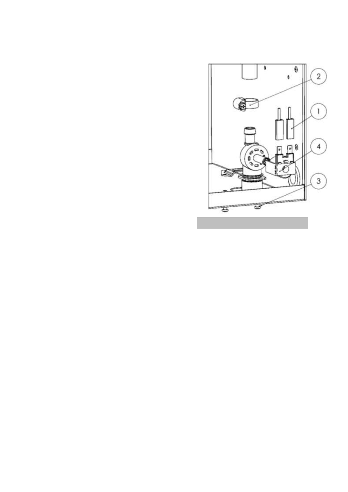
• Disconnect the power cables from the water inlet valve of your
humidifier (Item 1).
• Loosen the clamp and remove the water supply hose. (Item 2)
• Unscrew the two screws securing the valve (Item 3).
• Pull out your valve, remove the filter with pliers and remove the
coil (Item 4) by prying it off with a screwdriver.
• Run water through the valve body and over the filter to remove
any particles.
Once all these operations completed, please reassemble the unit, taking care to check the condition of the water
supply hose clamp. You can put your appliance back into service.
Ensure that all the clamps are properly tightened whenever the humidifier is maintained.
Fig. 6-4. Humidifier water inlet valve