Alltest-Agilent-Keysight-E9902G-Datasheet-29440-.pdf.pdf - 第19页
P a g e F i n d u s a t w w w . k e y s i g h t . c o m P a g e 18 Bi -directional Capacitance 160 pF (typical) 1. Frequency and cycle time depend on HybridPlus -DD Card options 6, 12, or 20. 2. Add ±1 ns for periods ove…

P
a
g
e
Find us at www.keysight.com Page 17
Maximum Current (pulsing)
700 mA
Maximum Switching Power
7.5 VA
HybridPlus-DD Card Receivers
Parameter
Specification
Programmable Receive Delay Time
Minimum
0 ns
Maximum
3.0 ms
Resolution
4 ns + 1% of vector cycle
Programming Resolution
1 ns
Maximum Input Voltage
12.0 V and
−
12.0 V
Parallel Capture RAM
128 bits
Pull-Up Curent Source
2.0 mA (typical)
Pull-Down Curent Source
5.0 mA (typical)
Receiver Threshold Voltage Range
Low Threshold
−
3.5 to 5.0 V
High Threshold
−
3.5 to 5.0 V
Programming Resolution
2.2 mV (typical)
Accuracy
±100 mV
Input Bias Current
±30 µA
Input Capacitance
83 pF
Disconnected Capacitance
12 to 23 pF (typical)
Bi-directional Capacitance
160 pF (typical)
HybridPlus-DD Card Drivers
Parameter
Specification
Frequency Range as a Clock
Minimum
625 kHz
Maximum
1
6.25, 12.5, or 20 MHz
Programming Resolution
2
1% of frequency
Programmable Vector Cycle Time
Minimum
1
160, 80, or 50 ns
Maximum
1.5 ms
Resolution
2
1% of vector cycle
Programming Resolution
1 ns
Peak Backdrive Current
−
3.5 to + 5.0 V source
750 mA
−
3.5 to + 5.0 V sink
−
500 mA
Continuous Output Current
Maximum Continuous Source Current
100 mA
Maximum Continuous Sink Current
100 mA
Slew Rate (into 100 ) Rising and Falling
Minimum
25 V/µs
Maximum
275 V/µs
Programming Resolution
25 V/µs
Driver Voltage
Range
3
−
3.5 to 5.0 V
Programming Resolution
2.206 mV
Static Accuracy (no load)
±100 mV
Minimum Pulse Width Generation (TTL)
50 ns
High-Impedance State Leakage Current
I
L
at V
O
= +3 V
25 to 150 µA
I
L
at V
O
=
−
2 V
−
150 to 0 µA
V
O
at I
L
= 0 A
−
0.7 to 0.7 V
Programmable Device Test Time-out
Minimum
5.0 µs
Maximum
429 s
Programming Resolution
100 ns
DC Output Resistance (at 500 mA)
1.15 to 2.0
Driver High-Impedance State Capacitance
125 pF (typical)
Disconnected Capacitance
12 to 23 pF (typical)

P
a
g
e
Find us at www.keysight.com Page 18
Bi-directional Capacitance
160 pF (typical)
1. Frequency and cycle time depend on HybridPlus-DD Card options 6, 12, or 20.
2. Add ±1 ns for periods over 100 ns.
3. Driver overvoltage trip points: 7.0 V and -5.5V.
AccessPlus Card
Parameter
High-Frequency
Ports
General-Purpose Instrument Ports
General-
Purpose Relays
Coax Mode
Differential Mode
Number of Ports
8
10 multiplexed to 28 pairs
24
Bandwidth: 3 dB point
100 MHz
25 MHz
45 MHz
6 dB point
176 MHz
50 MHz
100 MHz
Crosstalk: < 1 MHz
−
80 dB
−
45 dB
−
65 dB
Maximum Signal Voltage to Earth
100 V peak
100 V peak
200 V peak
100 V peak
Maximum Carrying/Switching Current
0.5 A
0.5 A
0.5 A
Maximum Power
7.5 VA
7.5 VA
40 VA
30 VA
Maximum Standoff Voltage to Earth
200 V peak
200 V peak
200 V peak
200 V peak
Maximum Power
82 dB
Utility Card
External Device
Parameter
Specification
Physical Dimensions
75 x 152.55 mm (2.953” x 6.006”)
(Nominal thickness of PCB = 0.062")
Component Placement
Both sides allowed; not exceeding 3 mm on the top side and 10 mm on the bottom side
Physical Interface
Samtec 30 position 1.27 mm Tiger Eye Header board-to-board connector with a stacking height of
6.35 mm (02 x 30 position connector used).
Inputs
1 USB port (via the 30 pin connector)
1 Ethernet port
Outputs
18 pins with disconnect relays to MINT pins (with 4 pins capable of up to 2 A each)
Power supply
5 V @ 500 mA (maximum), or 12 V @ 2 A (maximum),
or externally routed (maximum of 12 V @ 2 A)
Communication
Via USB 2.0 to the host PC/workstation
or Ethernet communication via a class 2 switch controller
Balanced Multiplexing Port
Parameter
Specification
Number of Port
2 x 1:4 mux
Bandwidth
3 dB bandwidth (at 35 MHz ± 3 MHz)
Crosstalk
< 1 MHz (–55 dB ± 2 dB)
Maximum Current
2 ± 0.5 A (carrying capability)
Impedance
Balanced mux = 75 per pair (estimated)
P
a
g
e
Find us at www.keysight.com Page 19
System Specification
Device Under Test (DUT) Power Supplies
DUT Supply Source
Output Ratings
N6751A Modular Power Supply
0-50 V, 0-5 A, 50 W
N6752A Modular Power Supply
0-50 V, 0-10 A, 100 W
N6773A Modular Power Supply
0-20 V, 0-15 A, 300 W
N6746B Modular Power Supply
0-100 V, 0-1 A, 100 W
N5747 Power Supply
0 to 50 V, 0 to 10 A, 500W
Input Voltage and Current
Power Option Matrix
Power Option
Voltage line-to-neutral
Full-Load Amps (FLA) for:
4-Module
2-Module
1-Module
3PD
200
24
18
13
220
24
18
13
230
24
18
13
240
24
18
13
3PY
208
24
18
13
220
24
18
13
3PN
220/380
16
10
9
230/400
16
10
9
240/415
16
10
9
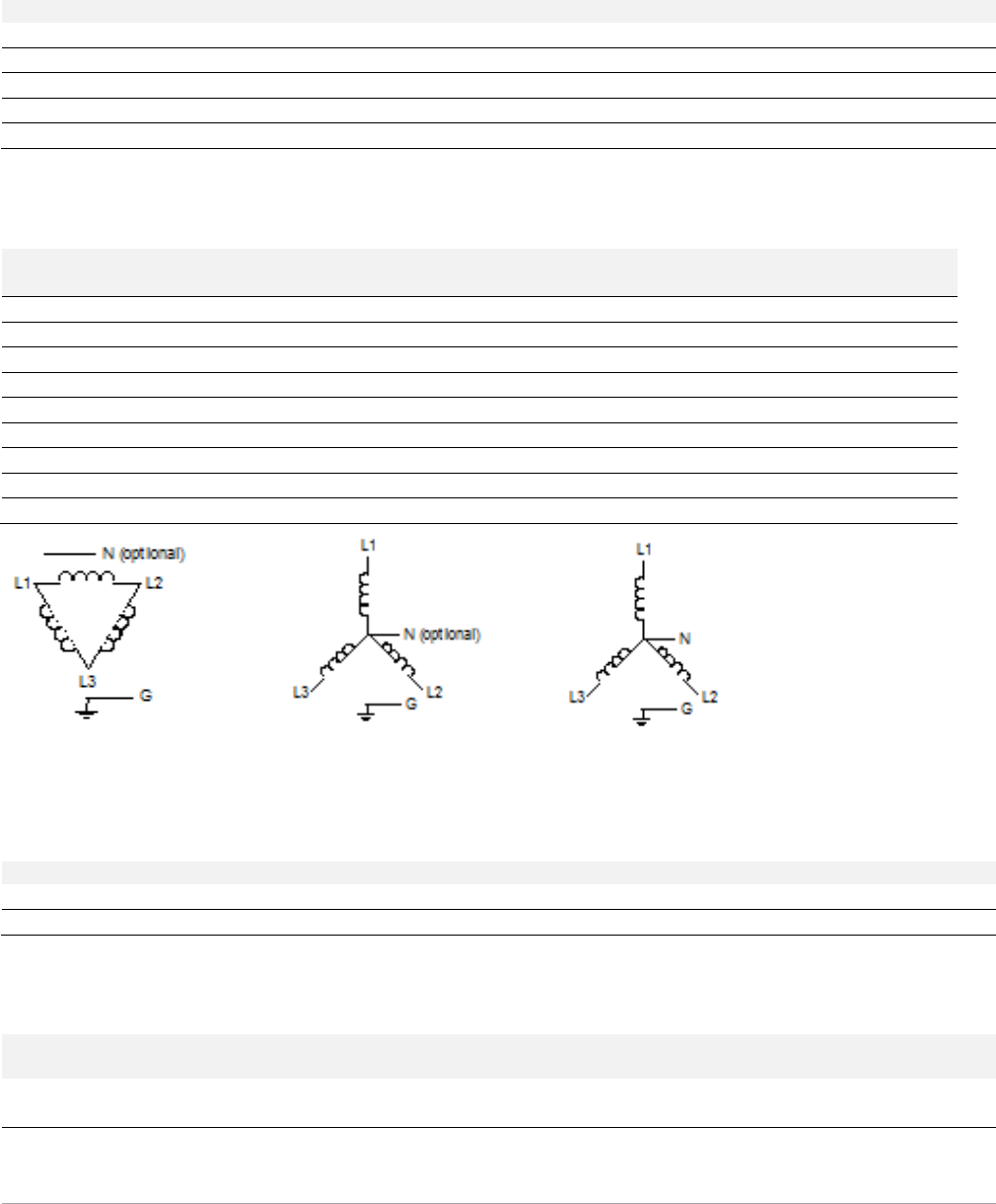
Three-Phase Delta* Three-Phase Wye* Three-Phase Wye with Neutral
* Neutral is not used by the systems for power options 3PD and 3PY. Neutral is shown in the diagrams because it is cabled into the PDU.
Environmental Requirements
Operating Temperature
Operating Humidity
Storage Temperature
Testhead
0°C to 40°C (32°F to 104°F)
5 to 80 % non-condensing
−
40°C to 70°C (
−
40°F to 158°F)
Controller
5°C to 45°C (41°F to 113°F)
20 to 80 % non-condensing
−
40°C to 65°C (
−
40°F to 149°F)
* Testhead over-temperature shutdown is typically at 55°C. Auto-adjust will occur automatically for ±5°C changes in temperature.
Dimensions and Weights
Width
Depth
Height
Weight
Four-Module System (E9903G)
Testhead
1490 mm
(58.66 in)
935 mm
(36.81 in)
887 mm
(34.92 in)
523 kg
(1153 lb)
Packaged for shipment
2134 mm
(84.02 in)
1219 mm
(47.99 in)
1377 mm
(54.21 in)
776 kg
(1710 lb)