Alltest-Agilent-Keysight-E9902G-Datasheet-29440-.pdf.pdf - 第3页
P a g e F i n d u s a t w w w . k e y s i g h t . c o m P a g e 2 Introduction The Keysight i3070 Series 6 I n-Circuit Test (ICT) system is designed t o bring industry- leading in-circuit testing technologie s into your …
P
a
g
e
Find us at www.keysight.com Page 1
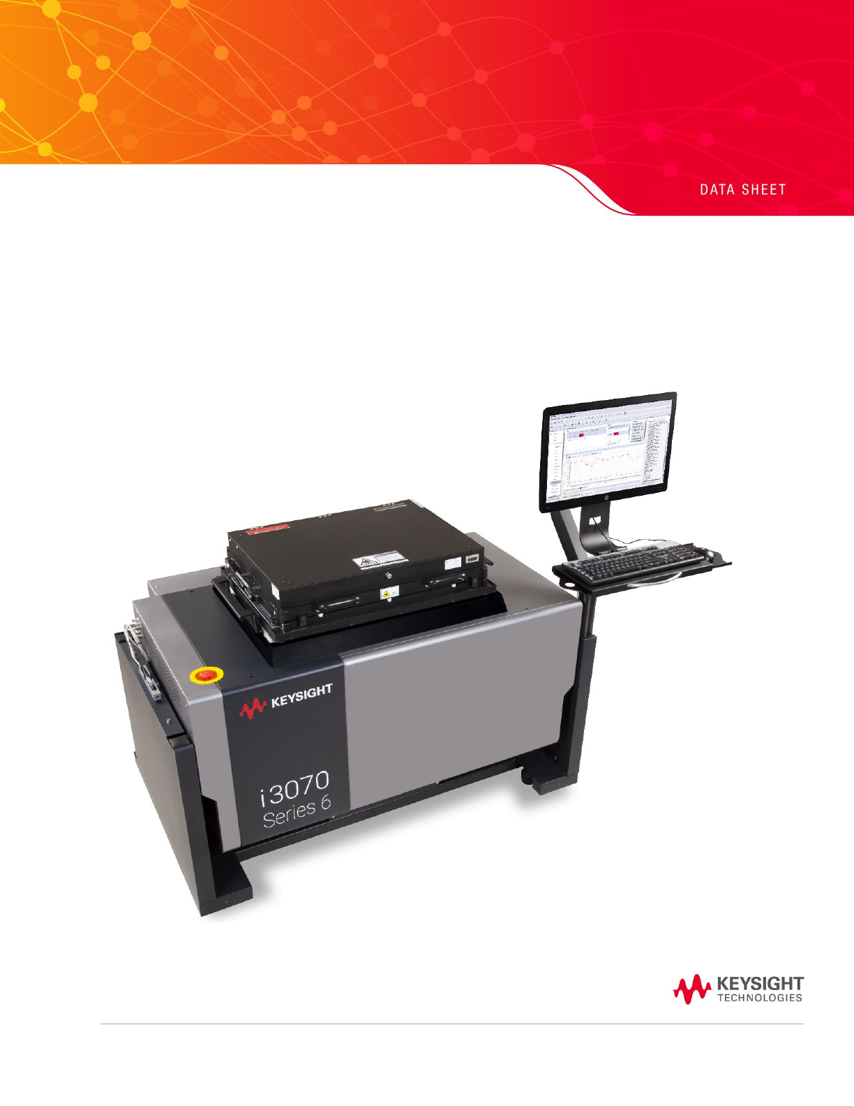
i3070 Series 6
In-Circuit Test Systems
Stay Connected. Evolve Continuously.

P
a
g
e
Find us at www.keysight.com Page 2
Introduction
The Keysight i3070 Series 6 In-Circuit Test (ICT) system is designed to bring industry-
leading in-circuit testing technologies into your Printed Circuit Board Assembly (PCBA)
manufacturing. This system is Industrial 4.0 ready and caters to in-circuit testing for a
wide range of PCBA sizes and applications such as Internet of Things, 5G
Communication, Automotive and Energy.
With a unique fixture design, i3070 offers the shortest signal path between measurement
circuitry and devices under test, this principle is the key to minimize undesired effects
from parasitic capacitance, improved immunity to crosstalk, and eliminate stray signal
coupling effects for a more consistent and repeatable measurement result.
i3070 Series 6 Family
i3070 Series 6 family offers a specific test capability that can be expanded in both
hardware and software capabilities to meet your future growth needs in your
manufacturing.
i3070 Series 6 family
Max Nodes
Foot Print
E9903G
5184
Width 1490 mm (58.66 in)
Depth 935 mm (36.81 in)
Height 887 mm (34.92 in)
E9902G
2592
Width 1490 mm (58.66 in)
Depth 935 mm (36.81 in)
Height 887 mm (34.92 in)
E9905G
2592
Width 954 mm (37.56 in)
Depth 935 mm (36.81 in)
Height 887 mm (34.92 in)

P
a
g
e
Find us at www.keysight.com Page 3
i3070 Series 6 System Summary
Mux System
UnMux System
Full System Node Capability
Max Node of E9903G
5184
5184
Max Node of E9902G
2592
2592
Max Node of E9905G
2592
2592
Full System Analog Capability
Shorts test programmable threshold
2 Ω to 1000
2 Ω to 1000
Resistance, Potentiometer measurements
0.1 Ω to 10 MΩ
0.1 Ω to 10 MΩ
Capacitance measurements
10 pf to 10 mf
10 pf to 10 mf
Inductance measurements
5 µH to 100 H
5 µH to 100 H
Diode measurements
± 0 V–19V
± 0 V–19V
Zener diode measurements
± 0 V–60V
± 0 V–60V
Transistor measurements (Beta)
10–1000
10–1000
FET measurements (On Resistance)
5 Ω–500 Ω
5 Ω–500 Ω
Fuse, Jumper, Switch measurements
0.1 Ω–500 Ω
0.1 Ω–500 Ω
Arbitrary waveform generator
1 Hz to 20 kHz
1 Hz to 20 kHz
Waveform digitizer
40k samples/sec, 8192 samples
Function generator (DC,
Sine, Square, and Triangle)
0 to ±10 V,
0.5 Hz to 20 kHz
0 to ±10 V,
0.5 Hz to 20 kHz
Auxiliary DC voltage source
0 to ±10 V; 30 or 150mA
0 to ±10 V; 30 or 150mA
DC detector
0 to 160 V
0 to 160 V
Universal counter: frequency, pulse, and time
interval measurements
1 Hz to 60 MHz; 30 ns to 1s
1 Hz to 60 MHz; 30 ns to 1s
Analog functional test access ports
E9903G:
8
E9903G:
8
E9902G
4
E9902G
4
E9905G
4
E9905G
4
Full System Digital Capability
Max Drive and Receive channels
E9903G:
576
E9903G:
5184
E9902G
288
E9902G
2592
E9905G
288
E9905G
2592
Pin-by-pin programmable drive and receive
resources
1 ns programming resolution
3.5 to +5.0 V logic levels 25 to
250 V/µs slew rate in 25 V/µs
steps, Pull-up/pull-down
2 ns programming resolution
0 to +5.0 V drive level 0 to
+4.875 V receive level
Pull-up/pull-down or AC
termination loads
Logic analyzer
bit-by-bit, and CRC capture
modes
bit-by-bit, and CRC capture
modes
Drive edge placement accuracy (any driver)
±5 ns (typical) ±700 mA
sourcing, 500 mA sinking
backdrive current
±15 ns (typical) ±750 mA peak,
±100 mA continuous backdrive
current
Drive voltage accuracy
2.206 mV programming
resolution
±100 mV
20 mV programming resolution
± 2% of setting ±20 mV