00193891-0702_AI_LP_Barcode_DE+EN.pdf - 第220页
2 PCB barcode scanner assembly instructions SIPLACE 2.11 PCB barcode scanner configuration 10/2009 Edition 220 4. The 'rest zone'. This empty zone surrounds the data matrix code. It conta ins no information and…
SIPLACE 2 PCB barcode scanner assembly instructions
10/2009 Edition 2.11 PCB barcode scanner configuration
219
Disadvantages: - the print quality of a barcode on the labels is a decisive factor in the scanning
result.
2.11.3 Structure of 2D barcodes
Barcode types: 2
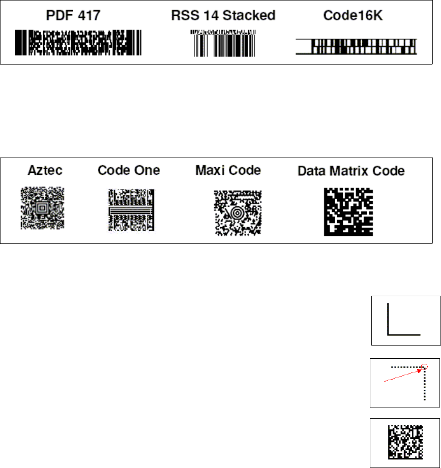
1. "Stacked" codes. These are essentially one-dimensional barcodes that are printed directly over
one another. Typical stacked barcodes include the PDF 417, RSS-14 Stacked and the 16K.
Fig. 2.11 - 2 Stacked barcodes
2. 2D barcodes, known as "matrix codes“ are another variant of the 2D barcodes. Again there are
various types commonly used, such as Aztec code, Maxi code, Code One and the data matrix
code.
Fig. 2.11 - 3 2D barcodes
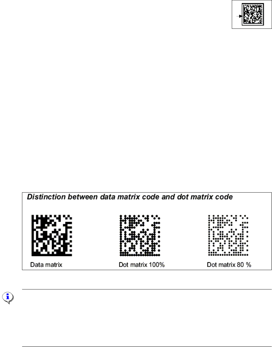
Data matrix code: The data matrix code consists of 4 main components. 2
1. The fixed dividing line ('corner’). This fixed dividing line
is used for pattern recognition and to calculate the rotary
position of the data matrix code.
2. The non-closed border (opposite corner). This
open corner is used to identify the number of lines and gaps.
This is known as the "matrix density“.
On the ECC 200, the
element in the top right-hand corner is white.
3. The storage area. This contains th
e binary information in coded
form. Depending on the cell size, it also defines the number of possible
items of information.
2 PCB barcode scanner assembly instructions SIPLACE
2.11 PCB barcode scanner configuration 10/2009 Edition
220
4. The 'rest zone'. This empty zone surrounds the data matrix code.
It contains no information and is no
t used for orientation.
The width of the rest zone is one field or one line.
The 2D barcode scanner can read both 1D and 2D barcodes.
They can be detected using a CCD chip.
Advantages of data matrix code:
– Flexible in terms of the range of applications
– Very high information density in the smallest space (over 2000 characters)
– Scanning is possible from any angle
– Minimal requirements in terms of c
o
lor contrast and print quality and thus suitable for direct la-
belers (e.g. laser labelers or needle embossing) as these requ
ire less contrast than for bar-
codes.
– Error correction using the "Reed-Solomon" algorithm - up to 25 % of the code may be dam-
aged.
Sample applications:
– Scanning permanent direct labels (e.g. on tools, motor components, drive parts, surgical in-
struments, etc).
– Production / manufacturing (identification of electro
n
ic components, tools, etc.)
– Chemical and biomedical analysis instruments
–PCBs
Fig. 2.11 - 4 Data matrix and DOT matrix barcodes
NOTE:
The barcode scanners that we use can read the following barcode types:
1D barcode scanner: Code 39, Code 128, Code 9
3, Codabar, EAN, EAN 128, UPC, 2/5 Inter-
leaved, Pharmacode
2D barcode scanner: Data Matrix ECC200 and 1D ba
rcodes Code 39, Code 128, Codabar, EAN,
EAN 128, UPC, 2/5 Interleaved
SIPLACE 2 PCB barcode scanner assembly instructions
10/2009 Edition 2.11 PCB barcode scanner configuration
221
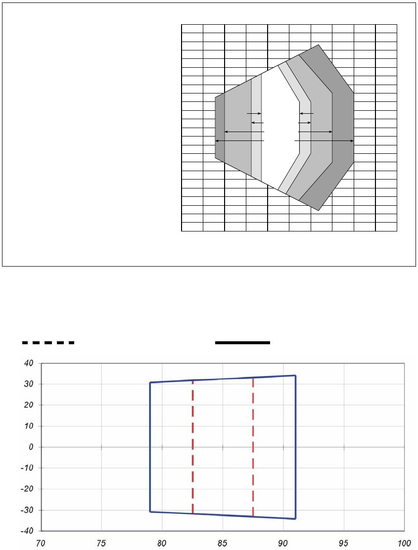
2.11.4 Scanning field diagram
0
20
-20
-40
-60
-80
-100
-120
40
60
80
100
120
0
150 200 250100
50
0.15 mm
0.20 mm
0.35 mm
0.5 mm
Leseabstand [mm]
L
ese
f
e
ldhöh
e
[
mm
]
Rasterscanner:
Rasterhöhe 15 mm bei
200 mm Leseabstand
Lesebedingungen:
siehe Tab. 10-1, Seite 10-1
Kennlinienfeld Scanfrequenz/
Leseabstand:
siehe Abb. 10-4, Seite 10-3
Linien-/Rasterscanner mit
Winkelvorsatz 105°:
das gesamte Lesefeld verschiebt
sich um 15 mm zum Lesefenster hin
CLV
422
-
0010
CLV 422-1010
Scanning field height [mm]
Grid scanner:
Grid height 15 mm for
200 mm scanning distance
Line/grid scanner with
105° angle attachment:
the entire scanning field moves by
15 mm towards the template win-
dow
Scanning distance [mm]
2
Fig. 2.11 - 5 Scanning area (DOF) for line/grid scanners (CLV 422)
Scanning diagram ICR850-1920S04
Scanning distance / mm
Scanning height
Specification 0.20 mm
Specification 0.35 mm
2
Fig. 2.11 - 6 Scanning area (DOF) for line/grid scanners (ICR 850-1920S04)