00193891-0702_AI_LP_Barcode_DE+EN.pdf - 第255页
SIPLACE 2 PCB barcode scanner assembly instructions 10/2009 Edition 2.11 PCB barcode scanner configuration 255 : Click on OK. : The FTP Image program do es not have to be open - it can run in background mod e. Th e "…
2 PCB barcode scanner assembly instructions SIPLACE
2.11 PCB barcode scanner configuration 10/2009 Edition
254
: Send the data to the barcode scanner (permanent download).
Select the
icon for this option.
Fig. 2.11 - 49 FTP Image
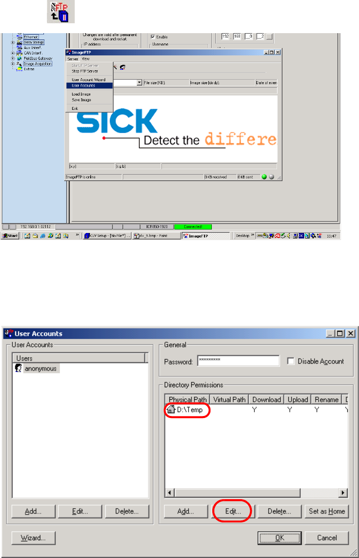
Define the path under which the images are to be saved.
: Select Server --> U
ser Accounts.
Fig. 2.11 - 50 Setting up the directory
: Click on the "Edit" button to change the existing directory.
SIPLACE 2 PCB barcode scanner assembly instructions
10/2009 Edition 2.11 PCB barcode scanner configuration
255
: Click on OK.
: The FTP Image program does not have to be open - it can run in background mode.
Th
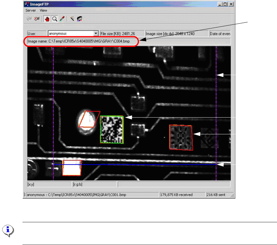
e "Diagnostic data" field in the "Image Acq." menu
can be activated for diagnostic purposes.
The analysis range (lilac lines), the invalid scan attempt
s (red lines) and the successful decoding
of the barcode (green line) are shown directly in the image.
The blue line indicates the end of the scanning process.
Blue line
Lilac line
Green line
Red line
Previously
set path
Fig. 2.11 - 51 Representation of a scanned barcode with diagnostic data
PLEASE NOTE:
The colored lines are only displayed i "Diagnostic data" was ticked under "Image request".

2 PCB barcode scanner assembly instructions SIPLACE
2.11 PCB barcode scanner configuration 10/2009 Edition
256
2.11.7.15 Possible sources of error
1. Problems establishing a connection
– Check the port ID and address
– Check cross-over cables
– With XP, deactivate and reactivate the network card (or reboot on an NT computer)
NOTE:
When you unplug the LAN cable, the connection on the CLV software remains "green".
When you plug in the LAN cable again, the connection must be established again.
Interface --> Options --> OK.
2.Problems snapping and assessing images
– The number of rows must be s
et to at least 4000
– Wait on external trigger
– The barcode to be read should be as close as possible to the beam
– Check the scanning distance if the image is fuzzy
3.Communication Monitor
– Host Interface: Set output to Ethernet. It is impo
rt
ant for production to reset it back to
Asynch. Host Interface.
– No result: Check the port ID or restart the program
– Quality assessment output
4.Barcode is not decoded
– Check the object velocity
– Check the cell size
5.Wrong or missing barcode in Sitest
– Enter /GN (enter again if you are in any do
ubt [se
lect from the list]) or check CR.
6.Auto Setup
– The barcode to be taught must be close to th
e scan
ning beam, as when snapping an image.
– The object velocity must b
e roughly correct