Specification SIPLACE CA-Series2014版.pdf - 第43页
43 Technical Data Siemens Signal Interface - Connector Assignment Signal interface (14-p ole connecting socket, interfac e standard 1.2) Upstream station X1 Downstream station X2 Pin 1 NOT READY + Pin 1 NOT READY + Pin 2…

42
Maximum Production Quality
Maximum Production
Quality
The SIPLACE CA-Series not
only provides leading
machine quality but also
guarantees maximum prod-
uct quality, through a combi-
nation of the following
features:
100% placement process
control
In its standard form, the
SIPLACE CA-Series fea-
tures various control mecha-
nisms which ensure
maximum placement reliabil-
ity. Sensors checks whether
the component was correctly
picked up or placed. The set-
down force of components is
checked and height differ-
ences during pickup and
PCB unevenness during
placement are compensated.
Digital vision inspection
The digital Vision system
ensures fast and reliable
component recognition, cou-
pled with user-friendly han-
dling. The system identifies
each individual component
by its geometry and color.
With the help of different illu-
mination levels and bright-
ness stages, almost every
component shape can be
easily recognized. The sys-
tem also saves images of the
components, so-called
"vision dumps", showing
which components have
been rejected.
This supports the early rec-
ognition of faults in new prod-
ucts and increases process
reliability. These Vision
dumps also serve as evi-
dence in the event of defec-
tive component supplies.
Intelligent software for
setup verification
The SIPLACE CA-Series
setups are verified with bar-
codes on the component reel
and by intelligent SIPLACE X
feeder modules. This helps
to avoid setup errors. This
network of checks consider-
ably lowers dpm rates and
increases the first pass yield.

43
Technical Data
Siemens Signal Interface - Connector Assignment
Signal interface (14-pole connecting socket, interface standard 1.2)
Upstream station X1 Downstream station X2
Pin 1 NOT READY + Pin 1 NOT READY +
Pin 2 NOT READY – Pin 2 NOT READY –
Pin 3 BOARD AVAILABLE + Pin 3 BOARD AVAILABLE +
Pin 4 BOARD AVAILABLE – Pin 4 BOARD AVAILABLE –
Pin 5 Not used Pin 5 Not used
Pin 6 Not used Pin 6 Not used
Pin 7 Not used Pin 7 Not used
Pin 8 Reserved Pin 8 Reserved
Pin 9 Reserved Pin 9 Reserved
Pin 10 Reserved Pin 10 Reserved
Pin 11 Reserved Pin 11 Reserved
Pin 12 Reserved Pin 12 Reserved
Pin 13 Reserved Pin 13 Reserved
Pin 14 Reserved Pin 14 Reserved
44
Technical Data
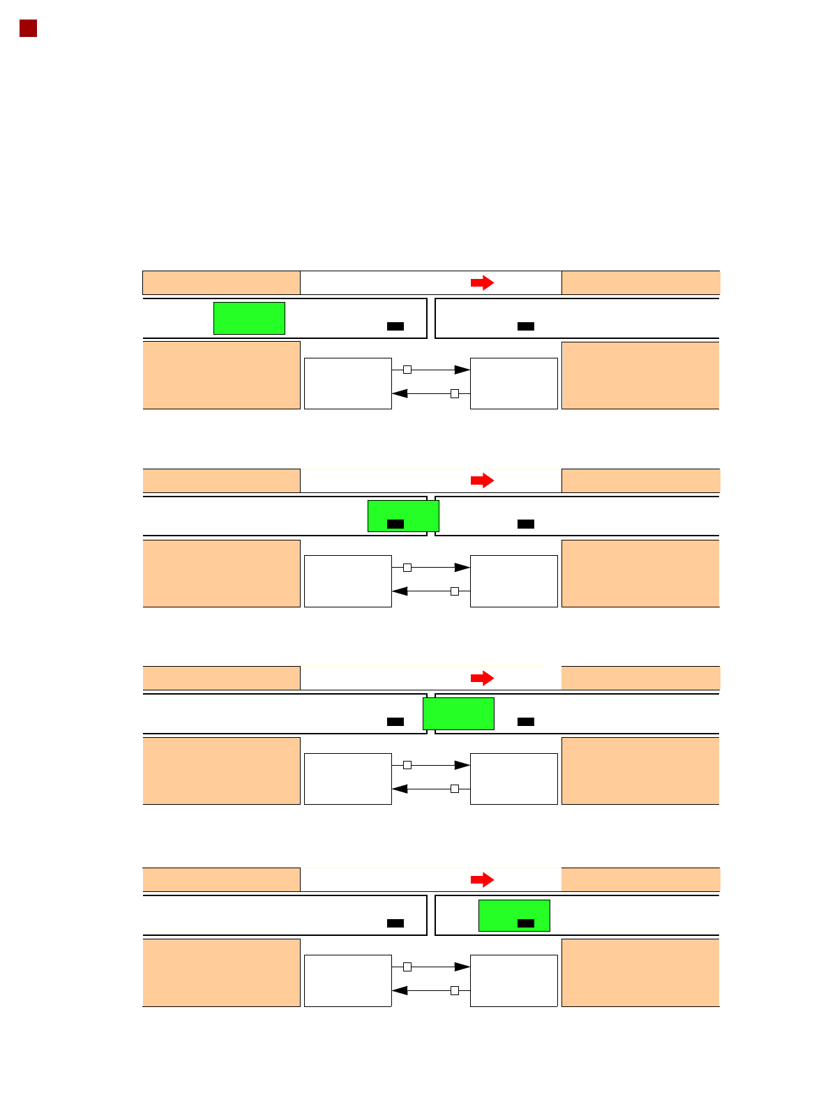
Siemens Signal Interface - Signal Sequence
1. After switching on the station
Transport direction
Belt n Belt n+1
PCB sensor PCB sensor
Station n transports PCB
to the transfer position
Belt n running Belt n+1 stopped
BOARD AVAIL-
ABLE
Permission
1
0
2. The PCB transfer has started
Transport direction
Belt n Belt n+1
PCB sensor
Station n transfers
PCB to Station n+1
Belt n running Belt n+1 running
Station n+1 expects
PCB from station n
3. PCB is transferred
Transport direction
Belt n Belt n+1
PCB sensor PCB sensor
Station n has
just transferred the PCB
Belt n stopped Belt n+1 running
Station n+1 expects PCB
from station n, but PCB
has not yet arrived.
PCB sensor
4. PCB transfer is complete
Transport direction
Belt n Belt n+1
PCB sensor PCB sensor
Station n
Belt n stopped Belt n+1 running
Station n+1
PCB arrived
Request
NOT READY
BOARD AVAIL-
ABLE
Permission
1
1
Request
NOT READY
BOARD AVAIL-
ABLE
Permission
0
1
Request
NOT READY
BOARD AVAIL-
ABLE
Permission
0
0
Request
NOT READY
To start a new PCB transfer, both signals must be "0" for at least 50 ms.
Station n+1
is not ready