4OM-1610-002_w.pdf - 第109页
4OM-1610 1-58 5. Consumables and Servicing Parts : Chap.1 Block Name Product Name Part No. Part Name Q'ty Recommended # of years Note(a) Exploded Illustration Remarks Main Unit T ouch Panel (Both Sides) 4U210136 EQU…
4OM-1610
1-57
5. Consumables and Servicing Parts : Chap.1
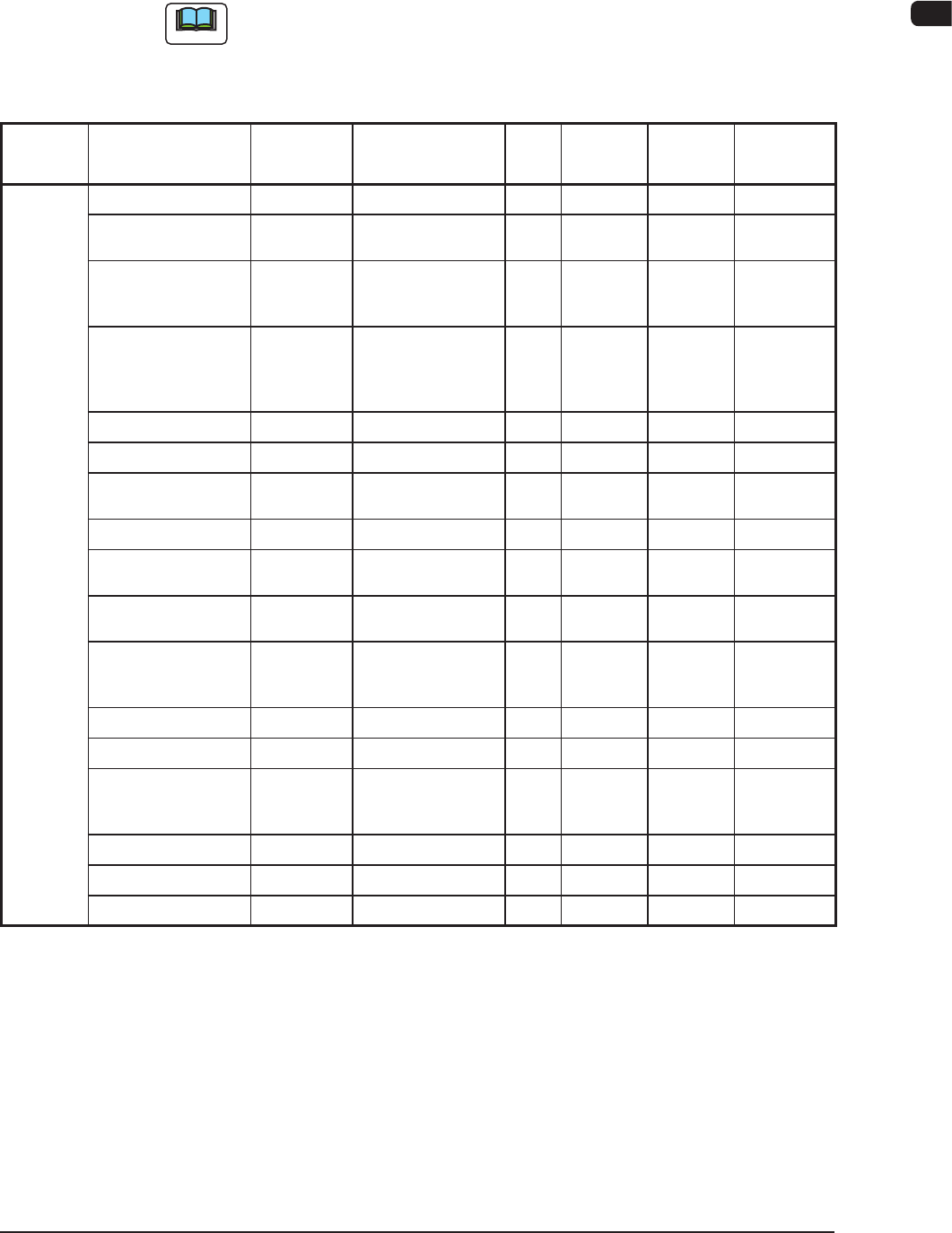
5.2 List of Servicing Parts
This component list is for the components for which maintenance is required in
several years, for your reference.
Note
For the maintenance procedure for the important maintenance components,
consult with our service personnel because high skill is required for such
maintenance.
Block
Name
Product Name Part No. Part Name Q'ty
Recommended
# of years
Note(a)
Exploded
Illustration
Remarks
Head
Section
Solenoid Valve 23D10016 ACCESSORY,SV 30 3 Fig. M-6
Nozzle Shaft ASSY
0916330J (*1)
0916331N (*2)
ASSY,GUIDE,LINEAR
30
Sets
- Fig. M-6 Note (c)
Hexagon Socket
Head Cap Screw
M2X4
221AA121 BOLT,HEX-SCT 30 - Fig. M-6 For Nozzle
Shaft Setup
Note (b)
O-Ring for Seal
Holder
226A0286
(S0-008-13)
0916D31E
(S0-010-12)
SEAL 30
90
2 Fig. M-6
Nozzle Shaft Spring 09160318 SPRING,COMP 30 2 Fig. M-6
Packing for Nozzle 226A0279 SEAL 60 - Fig. M-6
O-Ring for Filter
SO-008-11A
226A0276 SEAL 60 2 Fig. M-6
Line Sensor 23G00313 SENSOR,PELEC 2 2 Fig. M-6
Diffusion Plate
(Outside)
213D1169 (*1)
0916D31G (*2)
DISK 2 - Fig. M-6 Note (c)
Diffusion Plate
(Inside)
213D1336 (*1)
0916D31F (*2)
DISK 2 - Fig. M-6 Note (c)
Hexagon Socket
Head Cap Screw
M1.6X4
221AA332 BOLT,HEX-SCT 14 - Fig. M-6 For Diffusion
Plate Setup
Note (b)
Top Block 211G6373 BLOCK 30 - Fig. M-6
Cam Follower (f2.5) 222H0163 CAMFOLLOWER 30 - Fig. M-6
Hexagon Socket
Head Cap Screw
M1.6X3
221AA330 BOLT,HEX-SCT 60 - Fig. M-6 For Top
Block Setup
Note (b)
Sensor PM-U24 23G20046 SENSOR,PHOTO 2 3 Fig. M-4
Sensor PM-L24 23G10059 SENSOR,PHOTO 10 3 Fig. M-4
Slip Ring 0916D30T COUPLING 2 2 Fig. M-5
T4A16
1011-002

4OM-1610
1-58
5. Consumables and Servicing Parts : Chap.1
Block
Name
Product Name Part No. Part Name Q'ty
Recommended
# of years
Note(a)
Exploded
Illustration
Remarks
Main Unit Touch Panel
(Both Sides)
4U210136 EQUIPMENT 1 3 Fig. FA-1
Vacuum Pump 24A00420 VACUUM,PUMP 1 - Fig. B-3
Transfer
Unit
Transfer Pully 223Q0663 PULLEY,TIMING 24 5 -
Transfer Pully 223Q0755 PULLEY,TIMING 4 5 -
Transfer Pully 223M0059 PULLEY,TIMING 20 5 -
Transfer Belt 223L0383 BELT,TIMING 4 3 -
Transfer Belt 223L0384 BELT,TIMING 8 3 -
Cutter
Section
Cutter Block ASSY 0920712V GUIDE 1 2 -
T4A17
Note
(a) The recommended year of pieces is the value for reference only.
(b) Do not reuse any bolt removed during maintenance.
(c) *1 shows the case of using the diffuser plate (fan) and *2 shows the case of
not using such plate.
1011-002

4OM-1610
1011-002 2-A
Chapter 2
Troubleshooting
In this chapter the outlines for each trouble shooting are described.
1. Descriptions for Trouble Shooting
2. Management Information
3. Machine Information
4. "Error" Window