speedline 680SD Pump .pdf - 第10页
680SD BRUSHL ESS SERVO PUM P Pump Set up 8 680SD B rushless Servo Dri ven Pump Pump Setu p Int roduct ion Before running the pump for the first time or af ter cleaning or repairs you need to adjust the lif t height and t…

.
.
.
.
.
680SD BRUSHLESS SERVO PUMP
Syringe Air Connections
Operation and Maintenance Guide 7
Syringe Air Connections
Procedure Connect syringe air as follows:
1. Attach the appropriate syringe adapter to the top of the syringe. Install the
syringe by twisting it clockwise onto the Luer Lock fitting on the feed tube assem-
bly. Use care to prevent over tightening of the syringe damaging the threads.
Damaged threads will cause material to leak out of the fitting.
2. Attach the syringe air as follows: S1= Right/Primary Syringe 1 air supply (Or) S3=
Left/Secondary Syringe 2 air supply.
Attention
S2 and S4 are not used with 680SD pumps.
680SD BRUSHLESS SERVO PUMP
Pump Setup
8 680SD Brushless Servo Driven Pump
Pump Setup
Introduction Before running the pump for the first time or after cleaning or repairs you need to
adjust the lift height and the flow rate. You must have material in the pump before
running. Otherwise damage to the leadscrew and/or needle could result.
Attention
Set-up of the pump must be done with a needle installed on pump. If a needle is not
installed, the lift height cannot be set.
In this Section Refer to the following:
Topic See Page
Initial Lift Height Adjustment 9
Checking Lift Height 11
Fine Tuning Lift Height 12
.
.
.
.
.
680SD BRUSHLESS SERVO PUMP
Initial Lift Height Adjustment
Operation and Maintenance Guide 9
Initial Lift Height Adjustment
Introduction Lift Height determines how much material is allowed to enter the needle during a
dispense cycle.
The lift height must be correct:
• To ensure the proper flow rate of material.
• To prevent leakage when not dispensing.
• To prevent damage to the lead screw and/or needle caused by excess force
(Insufficient gap).
Procedure To perform Lift Height adjustment:
1. Make sure a needle has been installed on the pump cartridge.
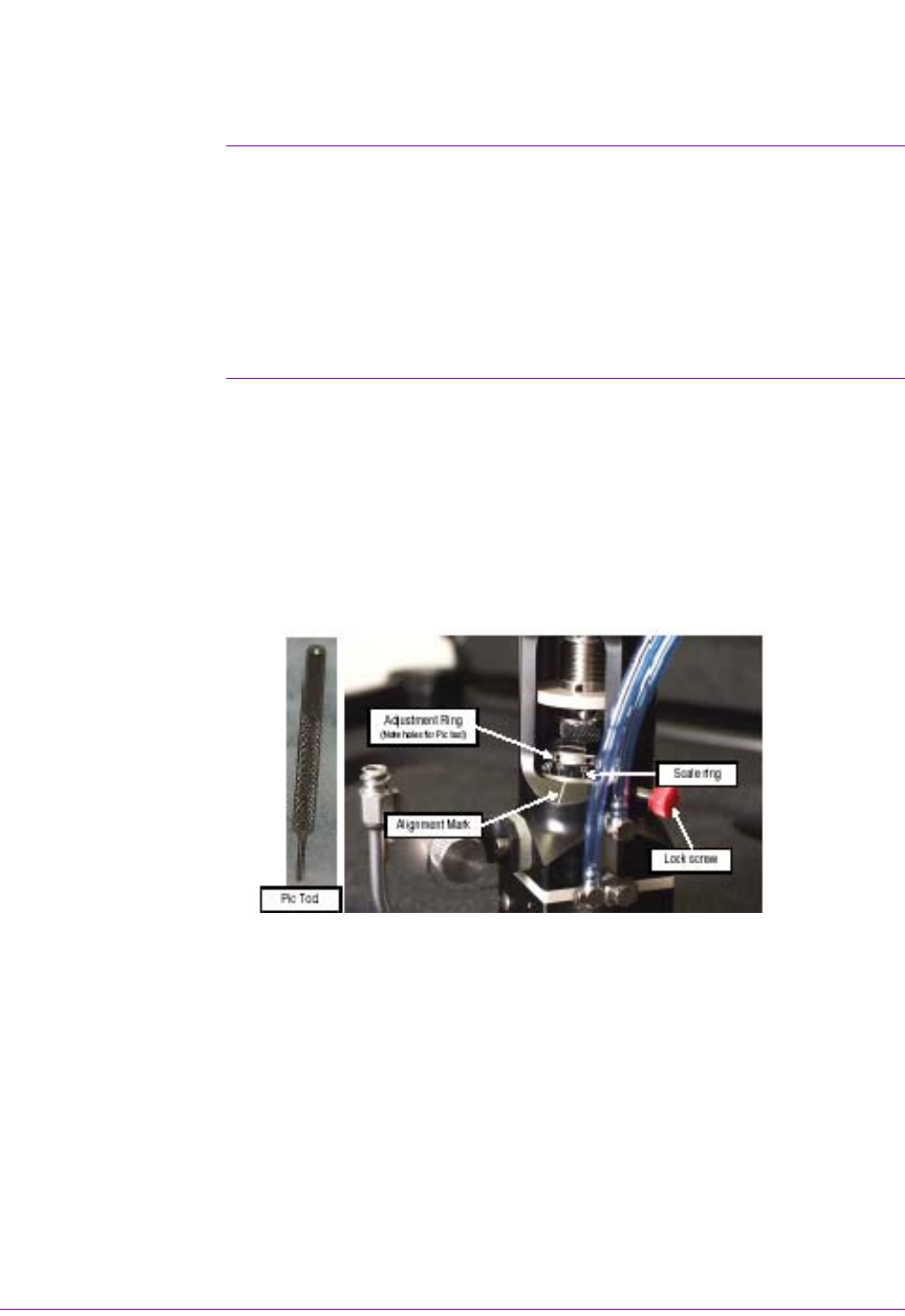
2. Loosen the red lock screw to release the adjustment ring and scale ring.
3. The adjustment ring and scale ring are visible through the access cutaway in the
pump body (see Figure 2).
4. Insert the pic tool (provided in the support kit) into a hole in the adjustment ring.
5. Using the pic tool as a lever, rotate the adjustment ring counter-clockwise until
the setscrew in the side of the scale ring is visible.
Figure 2
6. Loosen the set screw in the scale ring with the .035" Allen wrench (provided in
the pump support kit) until you are able to turn the scale ring and adjustment ring
independent of each other.
7. Leave the Allen wrench in the setscrew and rotate the adjustment ring clockwise
until resistance is felt. Resistance is felt when contact is made between the ball
on the end of the leadscrew and the ball seat in the needle.
8. Using the Allen wrench as a lever, rotate the scale ring clockwise until the zero
(0) lines up with the white alignment mark on the pump body.
9. Tighten the setscrew in the scale ring. The scale ring and adjustment ring are
now locked together.