speedline 680SD Pump .pdf - 第8页
680SD BRUSHL ESS SERVO PUM P Pump Pne umatic Connections 6 680SD B rushless Servo Dri ven Pump Pum p Pn eumat ic Con necti ons Int roduct ion The 680 SD incorpo rates a p recision mechanism which raises th e leadscrew to…

680SD BRUSHLESS SERVO PUMP
Pump Pneumatic Connections
6 680SD Brushless Servo Driven Pump
Pump Pneumatic Connections
Introduction The 680SD incorporates a precision mechanism which raises the leadscrew to allow
the flow of material through the needle when a dispense command is executed. At the
end of the dispense cycle the leadscrew is lowered, sealing off the end of the needle
preventing material seepage. Two air connections are required for each pump. One
raises and the other to lowers the leadscrew.
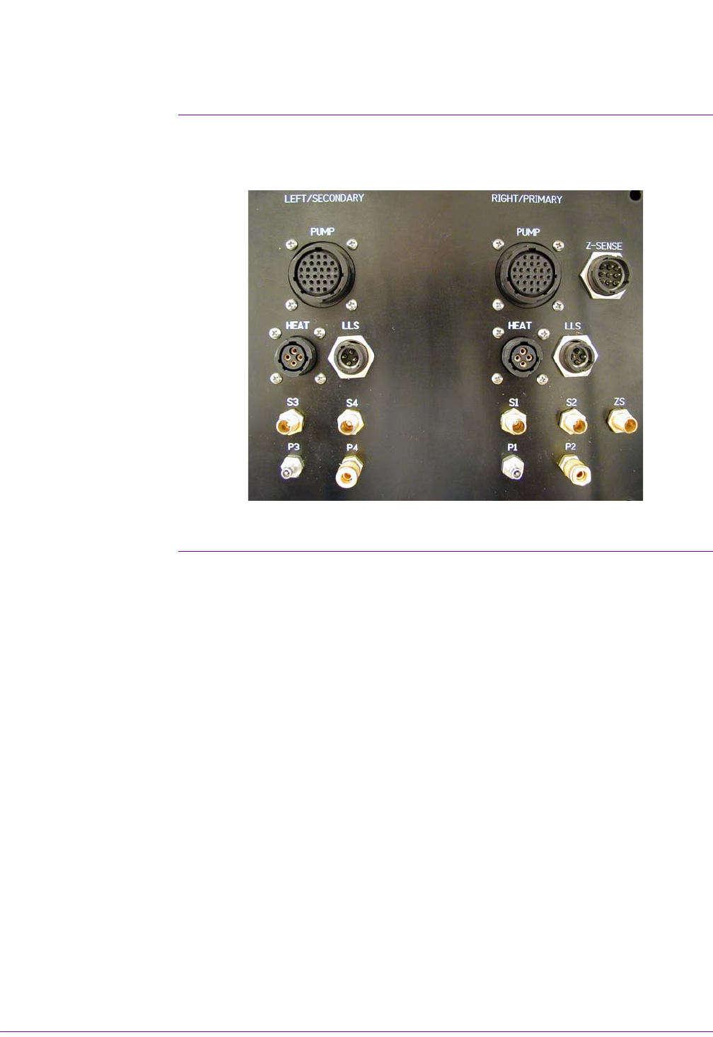
Procedure Air pressure to P1-P4 is factory preset to 60 PSI (max). This air supply is used to open
a valve (P1, P3) during dispense and close it (P2, P4) after dispense. Connect to the
dispense panel using the appropriate quick disconnect fittings as follows (see Figure 1
and Figure 7)
• P1= Right Primary Valve Open
• P2= Right Primary Valve Close
• P3= Left Secondary Valve Open
• P4= Left Secondary Valve Close

.
.
.
.
.
680SD BRUSHLESS SERVO PUMP
Syringe Air Connections
Operation and Maintenance Guide 7
Syringe Air Connections
Procedure Connect syringe air as follows:
1. Attach the appropriate syringe adapter to the top of the syringe. Install the
syringe by twisting it clockwise onto the Luer Lock fitting on the feed tube assem-
bly. Use care to prevent over tightening of the syringe damaging the threads.
Damaged threads will cause material to leak out of the fitting.
2. Attach the syringe air as follows: S1= Right/Primary Syringe 1 air supply (Or) S3=
Left/Secondary Syringe 2 air supply.
Attention
S2 and S4 are not used with 680SD pumps.