4OM-1064-001.pdf - 第147页
Tg0249-PM-MM 6.9 PICK-UP LOCA TION Display CAUTION Only a well-trained personnel shall perform teaching operations. The component library data and the pattern program may be modified additionally for the teaching. If the…
Tg0249-PM-MM
6.8.9 Teaching Operation with Trackball
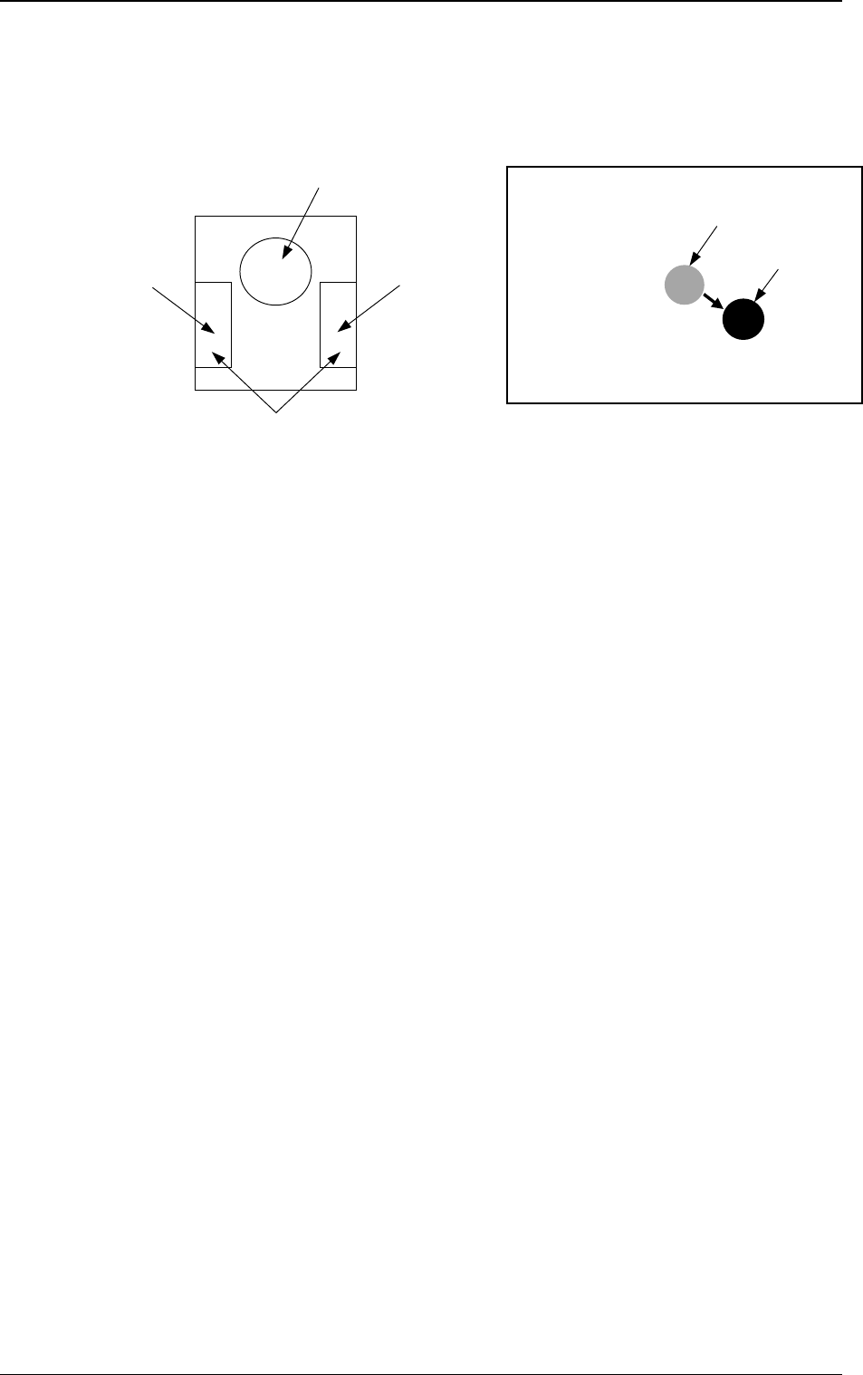
(1) When the manual alignment and teaching operations are implemented,
the captured image and the template for teaching appear on the recogni-
tion monitor.
(2) Use the trackball to move the template and align it with the teaching
point.
(3) When you press the right button of the trackball, the image size extends.
Pressing the left button reduces the image size. Adjust the size so that the
template and the teaching point overlap each other.
(4) Press the left and right buttons of the trackball simultaneously. The posi-
tion is determined.
0004-002 3-100
6. TEACH OFFSET Display
Fig. 3.64-2Fig. 3.64-1
Right Button
Function: Image
Extension
Left Button
Function: Image Reduction
Pressing the left and right buttons simultaneously:
Determination of Position
Template
Image
Image on Recognition Monitor
Trackball
Function: Template Movement
Tg0249-PM-MM
6.9 PICK-UP LOCATION Display
CAUTION
Only a well-trained personnel shall perform
teaching operations.
The component library data and the pattern
program may be modified additionally for the
teaching.
If the teaching operation is not performed cor-
rectly, the pick-up rate may deteriorate.
• The pick-up position of the component at each feeder is taught through
manual alignment operation.
The objective feeders for teaching are those whose pick-up position is reg-
istered in the component data of the current pattern program.
The pick-up rate may be improved after the teaching of the pick-up position
is performed when the pick-up rate is low.
• When the center of the cross lines does not match the center of the compo-
nent on the recognition monitor during teaching operation, perform the teach-
ing operation of the feeder (B) offset data.
• When a component has a groove, a protrusion, etc., and cannot be picked up
at the center without any hindrance, it is possible to perform the teaching
operation on the designation of eccentric pick-up (Chuck Location Adjust-
ment X and Y in Component Library Data).
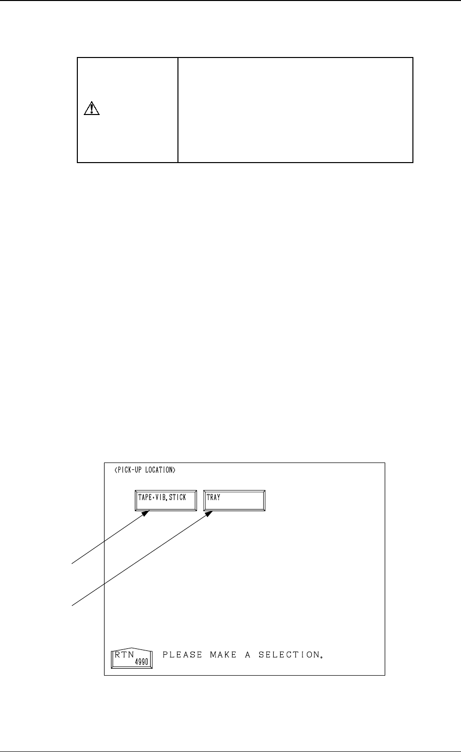
When the [PICK-UP LOCATION] key is pressed at the “TEACH OFFSET”
display, the following display appears on the screen.
This display can also be opened from the “AUTO OPN. SUB-MENU”
display. (Hierarchical Sequence: “AUTO OPN MODE <PLACEMENT>”
Display → “AUTO OPN. SUB-MENU” Display)
Note: This key can be selected only when the machine is in the “STOP”
mode.
9910-001 3-101
6. TEACH OFFSET Display
Fig. 3.65
*2
*1

Tg0249-PM-MM
*1 [TAPE VIB. STICK] Key
When this key is pressed, the “PICK-UP LOCATION (TAPE
VIB. STICK)”
display appears on the screen.
Perform the offset teaching operation on the following parameters through
manual alignment operation.
• PICK-UP LOCATION ADJUSTMENT X, Y in the component library
data
• FEEDER (B) OFFSET X and Y
• OFFSET X, Y in the component data
*2 [TRAY] Key (Option)
When this key is pressed, the “PICK-UP LOCATION (TRAY)” display
appears on the screen.
Note: This display cannot be opened while the pallet is being drawn out.
Perform the offset teaching operation on the following parameters through
manual alignment operation.
• PITCH X (mm), Y (mm) and SIDE LG. X (mm), Y (mm) in the compo-
nent library data
• FEEDER (B) OFFSET X and Y
• OFFSET X, Y and PICK-UP LOCATION ADJUSTMENT X, Y
9910-001 3-102
6. TEACH OFFSET Display