00194932-20 User Manual CAN Test Box-Error Frame Diagnostic unit_en.pdf - 第105页
1 - 105 Edition 10/2 018 SIPLACE CAN Bus 105 4.1 1 CAN Bus structure SIPLACE SX / DX-Series CAN Bus card in the Box PC 627B 4 The CAN Bus card (03052590 ) is a PCI plug-in card and is located in the BoxPC. For easy acces…
1 - 104
SIPLACE CAN Bus Edition 10/2018
104
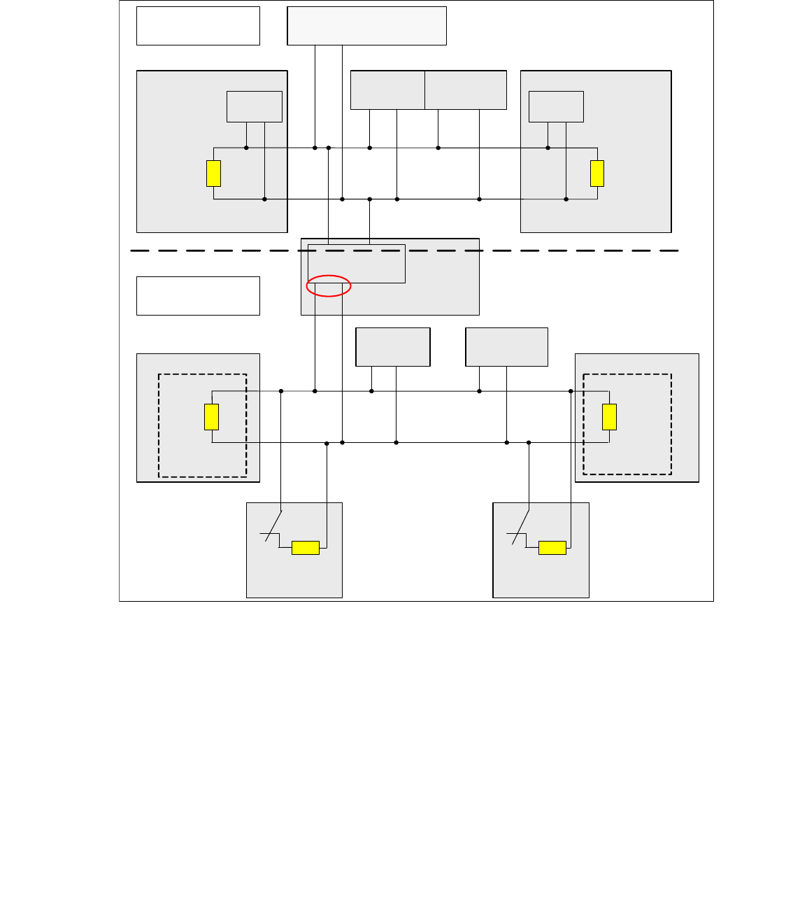
4.10.6 CAN Bus with CAN Terminator on the D4 in detail
For the D-Series machine we use two different CAN Bus circuits with a different speed. The ma-
chine CAN Bus with 1Mbit/s and the CAN Bus for the component table and tape cutter with 500
kbit/s. The speed of the CAN Bus will be reduce on the CAN Interface board which is located on
the CAN I/O module.
Fig. 4.10 - 11 CAN Bus in detail for example PA1 D4 machine
Note to measure the CAN terminator:
In General, the terminator has to measure if the machine switch off!
In the Fig. 4.10 - 11 for the component and tape cutter CAN Bus (500kBit/s), there are four termi-
nators in the circuit, if the machine switch off and the component table connected. So you measure
on position (1) 30 ohm.For the machine CAN Bus (1MBit/s) you measure 60 ohm
When the machine is switch on, the Relays contacts K1 will be open and the normal termination
of 60 Ohm is available. Now, If you change or disconnect a component table, the CAN Bus is
working normal, because the relay contact K1 will be closed and the other terminator is available .
Component Table 1Component Table 4
Gantry head distributer
Gantry 4
TQ M
CAN_H igh
CA N_Low
Machine CAN Bus
1 Mbit/s
CAN Bus for
Component table and
tape cutter 500 kbit/s
Axis unit 1/4
PA 1
Transport
control unit
Micro BOX PC
(Machine controller)
Gantry head distributer
Gantry 1
TQ M
CAN_H igh
CAN_Lo w
CAN
I/O module
sector 4
CAN Interface
500 KBit/s
CAN_High
CA N_Low
CAN_High
CAN_Low
Com. unit
Tape cutter
Location 1
Tape cutter
Location 4
Com. unit
CAN Bus
Terminator
Comp.table 1
CAN Bus
Terminator
Comp.table 4
120 Ohm120 Ohm
120 Ohm
120 Ohm
Relays
contact K1
Relays
contact K1
1
1 - 105
Edition 10/2018 SIPLACE CAN Bus
105
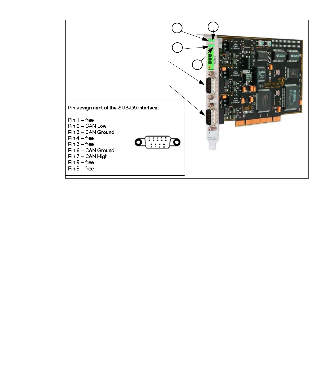
4.11 CAN Bus structure SIPLACE SX / DX-Series
CAN Bus card in the Box PC 627B 4
The CAN Bus card (03052590) is a PCI plug-in card and is located in the BoxPC.
For easy accessible service on both connected machine CAN cables (CAN 1 / CAN 2) there is an
SUB-D9 connector attached.
Fig. 4.11 - 1 CAN Karte PowerCAN-PCI (03052590-0x)
(1) L2- flashes, if CAN channels initialized
(RUN Status)
(2) Shows Communication CAN Bus 1
(3) Shows Communication CAN Bus 2 (4) LED ON - Display Power 5V
1
2
3
4
Machine CAN Bus 2
Machine CAN Bus 1
1 - 106
SIPLACE CAN Bus Edition 10/2018
106
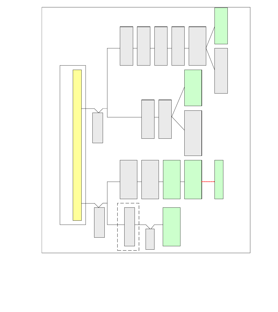
4.11.1 Machine CAN Bus structure SX1/DX1
The SX1/2 and DX 1/2 Machine are working with two CAN Bus circuits.They are divide in CAN 1
and CAN 2. Both CAN Bus circuits working with a speed of 1Mbit/s. CAN Bus 1 is reponsible to
supply the GCU (Gantry control unit) for the gantry and HCU (Head control unit) for the head with
data. The CAN 2 supplys the location (FCU, tape cutter), Transport control unit and stationary
cameras with data. For the sycoronization of the HCU‘s and GCU‘s we introduce an additional
CAN Bus, GCAN (Gantry CAN Bus). This CAN Bus is not used at the moment..
Fig. 4.11 - 2 Machine CAN Bus SX1 and DX1
C
O
M
U
n
i
t
CAN 2
X2pn
Transport control
unit 2
Machine CAN Bus
(MCAN Bus)
CAN 1
X1pn
Distributor unit Sector 2
Feeder control unit
(FCU 2)
Location 2
Stationary camera
(IC)
Location 2
I/O Module
Connector with
Terminator 120 Ohm
on X17ca
Trailing interface
Gantry 1
Station computer (Box PC)
Stationary camera
(IC)
Location 1
Stationary camera
(FC)
Location 1
Connector
for GCU 3
Transport control
unit 1
Gantry control unit
GCU 2
Gantry control unit
GCU 1
Basis adapter
Terminator 120 Ohm
Option WPC
Location 2
Terminator 120Ohm
Feeder control unit
(FCU)
Stellplatz 1
Service
connector
Service
connector
C&P20/CPP/TH-Head
Head
CAN Bus
Connector with
Terminator 120 Ohm
on X136
Machine CAN Bus
(MCAN Bus)
Connector with
Terminator 120 Ohm
on X116
Option WPC Location 1
Terminator 120 Ohm