00194932-20 User Manual CAN Test Box-Error Frame Diagnostic unit_en.pdf - 第109页
1 - 109 Edition 10/2 018 SIPLACE CAN Bus 109 Fig. 4.1 1 - 5 Machine and Gantry Can Bus st ructure SX1/2 and DX1/2 operating diagram 03055 284-02 C O T - I n s e r t 3 0 : 0 3 0 7 2 0 9 8 M a n u a l t a b l e 3 0 : 0 3 0…
1 - 108
SIPLACE CAN Bus Edition 10/2018
108
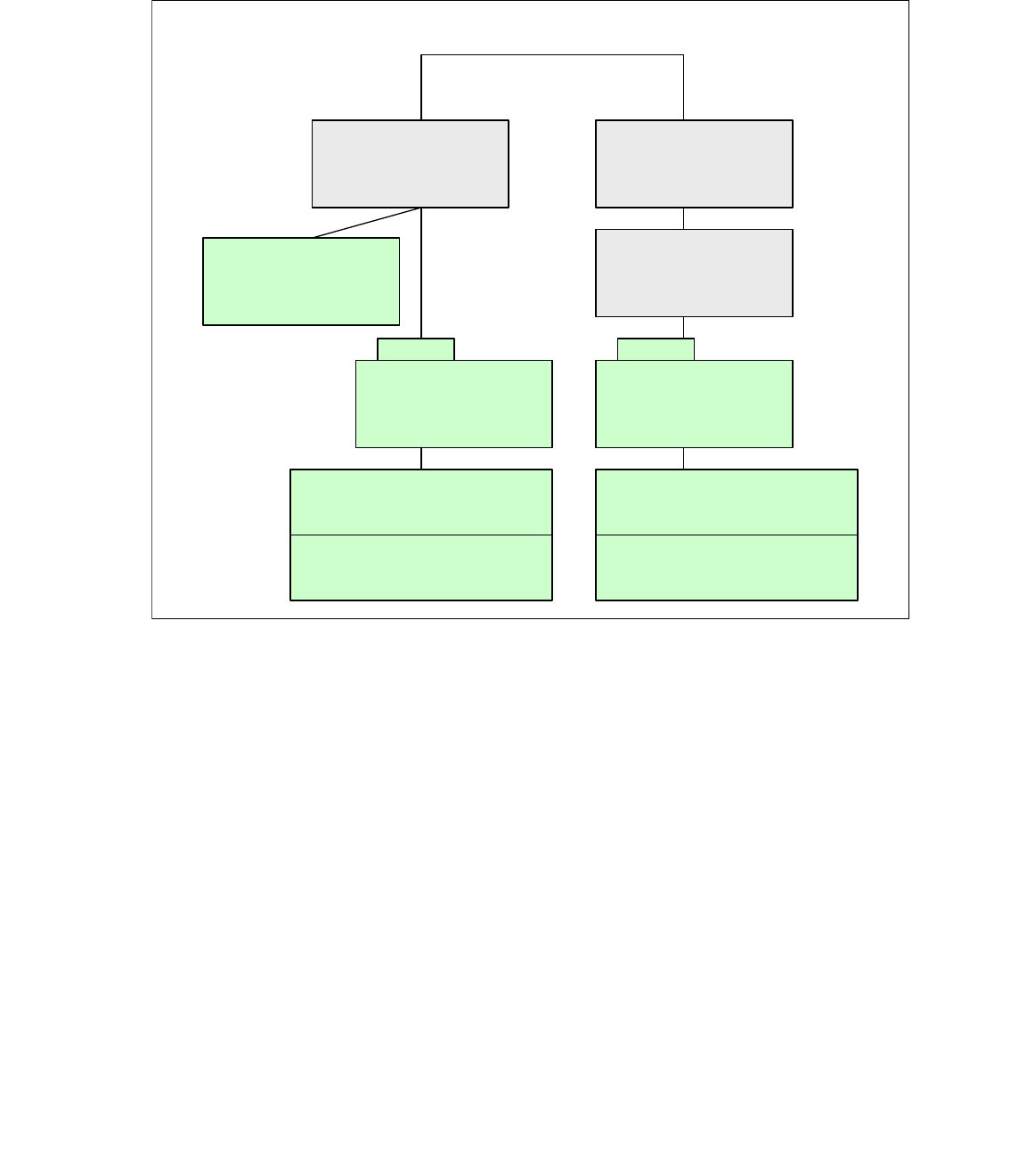
4.11.3 Gantry CAN Bus structure SX1/2 and DX 1/2
The Gantry CAN Bus is not used at the moment.In case of troubleshooting machine problems or
changing connector you have to know and check the CAN Bus. (see circuit diagram, too).
Fig. 4.11 - 4 GCAN Bus SIPLACE SX1/2 and DX 1/2
GCAN (Gantry - CAN Bus)
SX1/2
Trailing interface
Gantry 1
SX2
Trailing interface
Gantry 2
SX2
Gantry control unit
(GCU 3,
GCAN - CAN 2)
Gantry control unit
(GCU 2 / CAN 2)
Gantry control unit
(GCU 1 / CAN 2)
SX1
Terminator 120 Ohm
(X18ca)
X18ca
Head control unit
HCU 1 and HCU 2 for TH
Terminator 120 Ohm
X18aa
Head control unit
HCU 1 and HCU 2 for TH
Terminator 120 Ohm
1 - 109
Edition 10/2018 SIPLACE CAN Bus
109
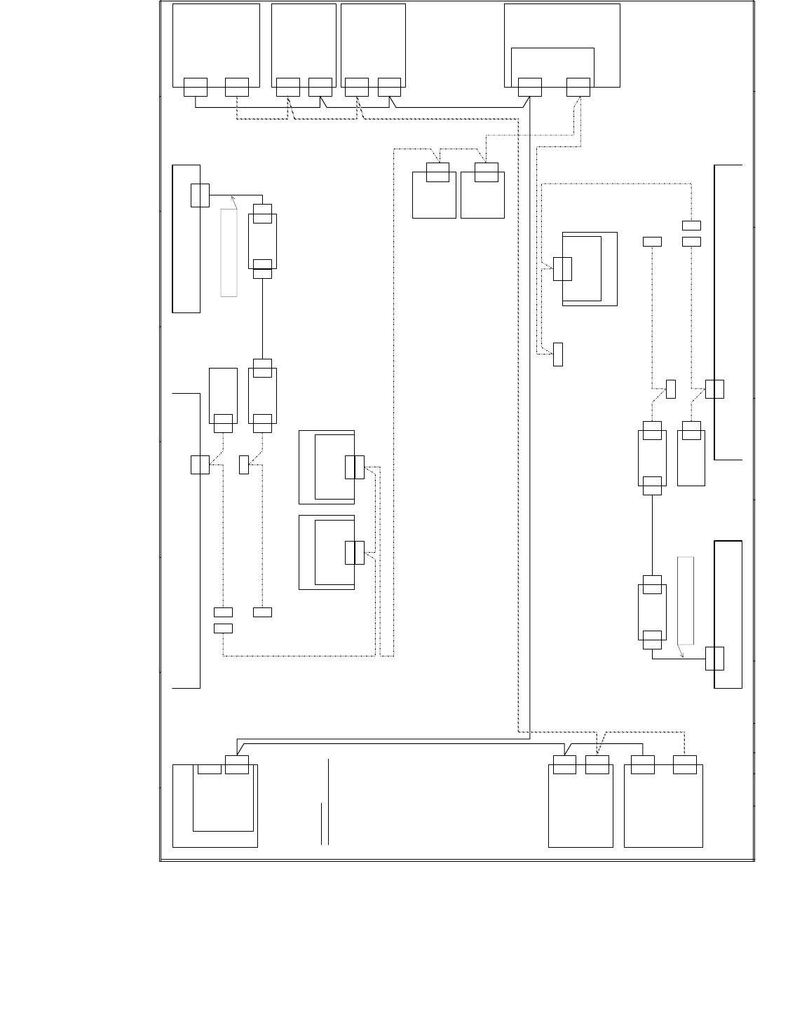
Fig. 4.11 - 5 Machine and Gantry Can Bus structure SX1/2 and DX1/2 operating diagram 03055284-02
C O T - I n s e r t 3 0 : 0 3 0 7 2 0 9 8
M a n u a l t a b l e 3 0 : 0 3 0 8 3 2 7 9
C A N b u s w i r i n g
w i r e n o . w i r i n g S u b - D - P I N
1 f r e e 1
2 G N D 6
3 C A N _ L 2
4 C A N _ H 7
5 G N D 3
6 f r e e 8
7 f r e e 4
8 f r e e 9
9 f r e e 5
X 1 p nX 2 p n
C A N c a r d
0 3 0 5 2 5 9 0
X 2 p n
C A N 1
G C U 3
0 3 0 5 2 2 0 0
( s a )
X 1 O u cX 1 U u c
C A N 1
( M C A N )
C A N 2
( G C A N )
C A N 2
F C U 1
F C c a m e r a , s t a t i o n a r y
X 1 0 d m
X 1 0 d m
B o a r d v i s i o n
L E D d r i v e r V L T 3 3
0 3 0 3 9 2 4 4 ( d m )
I C c a m e r a , s t a t i o n a r y
X 1 0 a m
X 1 0 a m
B o a r d v i s i o n
L E D d r i v e r V L T 3 3
0 3 0 3 9 2 4 4 ( a m )
X 1 0 b m
B o a r d v i s i o n
L E D d r i v e r V L T 3 3
0 3 0 3 9 2 4 4 ( b m )
I C c a m e r a , s t a t i o n a r y
X 1 0 b mX 1 0 c m
C A N 2
( G C A N )
C A N 1
( M C A N )
T a i l i n g i n t e r f a c e 2
0 3 0 6 4 1 2 7
( c a )
X 1 O u cX 1 U u c
X 1 7 c a
G C U 1
0 3 0 5 2 2 0 0
( u a )
X 1 U s c
C A N 2
( G C A N )
C A N 1
( M C A N )
X 1 O s c X 1 U s c
X 1 O s c
C A N 2
( G C A N )
C A N 1
( M C A N )
T a i l i n g i n t e r f a c e 1
0 3 0 6 4 1 2 7 ( a a )
G C U 2
0 3 0 5 2 2 0 0
( t a )
X 1 U t c
C A N 2
( G C A N )
C A N 1
( M C A N )
X 1 O t c X 1 U t c
X 1 O t c
C o n t r o l c o m p u t e r
0 3 0 5 5 3 0 0 ( p c )
X 1 7 c a
X 1 8 c a
X 1 8 c a
X 1 7 a a
X 1 7 a a
X 1 8 a a
X 1 8 a a
P C B c o n t r o l 2
D i s t r i b u t o r u n i t
0 3 0 6 5 8 9 2 ( q a )
C A N 1
( M C A N )
X 2 q b
C A N 2
I / O c o n t r o l u n i t
0 3 0 5 2 3 1 5 ( q b )
X 1 q b
X 1 q b
X 1 p n
X 7 a p
X 7 a p
P C B c o n t r o l 1
X 7 a o
X 7 a o
W P C 1
0 3 0 5 5 2 0 0 G C A N
* ) N o t e :
C o n n e c t t e r m i n a t i n g r e s i s t o r s
0 3 0 2 7 6 4 6
t o X 1 7 c a a n d X 1 8 c a i n 1 - g a n t r y m a c h i n e s .
* )
* )
0 3 0 5 2 2 1 8 C A N 2
S o
X 1 1 6
X 1 1 5
C A N I N
X 1 1 5
X 3 * p
X 3 * p
C O T - I n s e r t 6 0 : 0 3 0 6 0 4 7 1
M a n u a l t a b l e 6 0 : 0 3 0 8 3 0 9 3
T e r m i n a t i n g
r e s i s t o r
0 3 0 2 7 6 4 6
X 1
X 1 * q
X 1 1 5
X 3 * p
C O T - I n s e r t 3 0 : 0 3 0 7 2 0 9 3
M a n u a l t a b l e 3 0 : 0 3 0 8 3 2 7 3
C A N
S w i t c h
X 1 * q
X 2 * q
X 2 * q
C A N - B u s
T e r m i n a t o r
X 1
X 1
S t 2
S t 2
X 2
X 2
C O T - I n s e r t 3 0 : 0 3 0 7 2 0 9 7 - W 3
M a n u a l t a b l e 3 0 : 0 3 0 8 3 2 7 8 - W 3
C O T - I n s e r t 3 0 : 0 3 0 7 2 0 9 8
M a n u a l t a b l e 3 0 : 0 3 0 8 3 2 7 9
F C U 2W P C 2
S o
X 1 3 6
X 1 3 5
C A N I N
X 1 3 5
X 3 * p
X 3 * p
C O T - I n s e r t 6 0 : 0 3 0 6 0 4 7 1
M a n u a l t a b l e 6 0 : 0 3 0 8 3 0 9 3
T e r m i n a t i n g
r e s i s t o r
0 3 0 2 7 6 4 6
X 1
X 1 * q
X 1 3 5
X 3 * p
C O T - I n s e r t 3 0 : 0 3 0 7 2 0 9 3
M a n u a l t a b l e 3 0 : 0 3 0 8 3 2 7 3
C A N
S w i t c h
X 1 * q
X 2 * q
X 2 * q
C A N - B u s
T e r m i n a t o r
X 1
X 1
S t 2
S t 2
X 2
X 2
C O T - I n s e r t 3 0 : 0 3 0 7 2 0 9 7 - W 3
M a n u a l t a b l e 3 0 : 0 3 0 8 3 2 7 8 - W 3

1 - 110
SIPLACE CAN Bus Edition 10/2018
110
4.11.4 Measurement terminator (Resistor) on machine CAN Bus SX1/2
and DX1/2
On SX machines it is no longer possible to measure 60 Ohm between pin 2 and 7 on the CAN Bus
when the machine is switched off. At a switched-off machine with WPC or without WPC you have
to measure the following CAN resistance between pin 2 and pin 7.
Note:
With a configuration of an SIPLACE SX/DX machine and one WPC, the "PCB CAN-Bus-termina-
tor component table 03046863-xx" will be used. If there two WPC‘s installed, an additional retrofit
kit is necessary. The "Add-on kit COT-I30 CAN-Switch 2. WPC 03085518-xx" have to install on
both location, so you need two of this kits if you want to install an second WPC.
Checking the CAN Bus cable
Between pin 2 and 3 and between pin 7 and 3 there should be no connection
(approx. 1 to 3 MOhm ).
Attention: 4
Power fail signal is no longer in the CAN Bus cable. The Power fail signal is generated by the
25VDC Puls power supply unit and goes to the HCU and GCU directly.
without WPC 1x WPC connected 2x WPC connected
CAN1 CAN2 CAN1 CAN2 CAN1 CAN2
SX1/DX1 40 Ohm 60 Ohm 40 Ohm 40 Ohm -- --
SX2/DX2 30 Ohm 60 Ohm 30 Ohm 40 Ohm 30 Ohm 60 Ohm