00194932-20 User Manual CAN Test Box-Error Frame Diagnostic unit_en.pdf - 第12页
1 - 12 SIPLACE CAN Bus Edition 10/2018 12 Ordernumber Siplace CAN Bus Analysis tool: 03105007-01 Content: The following cables will be delivered with the ordernumber of the Siplace CAN Bus analysis tool. (1) 03050022-xx …
1 - 11
Edition 10/2018 SIPLACE CAN Bus
11
2 CAN Test Box
2.1 General
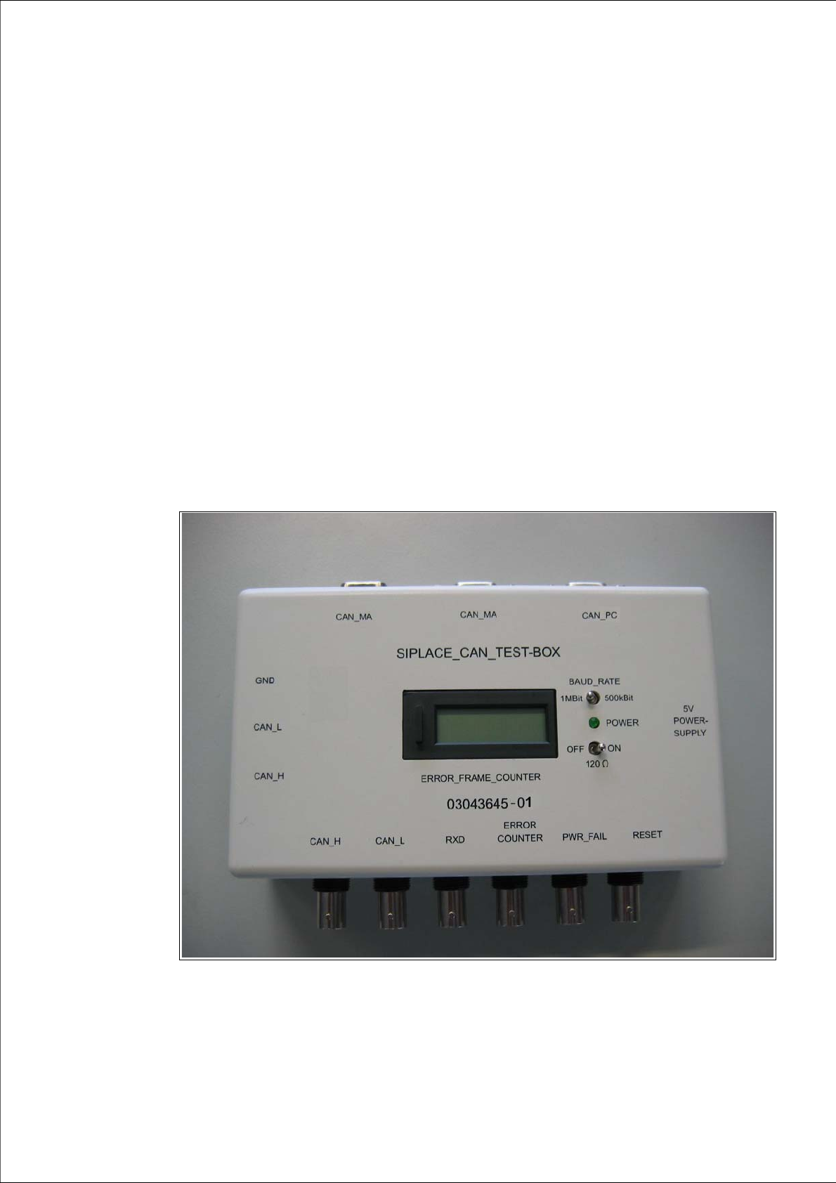
The CAN Test Box is a tool for service technicians to test basic CAN bus functions at SIPLACE
machines. This CAN Test Box can be used on machines implementing a CAN bus with a baud
rate of 500 kBit or 1 MBit. Although the CAN Test Box can also be used for the slower CAN bus
(125kBit) on HS50/60 machines, the Error Frame Counter will not function in this case.
The following functions can be checked:
– Terminating resistors
– Recessive voltage levels
– Dominant voltage levels
– Power fail voltage level, CAN reset
– Error frames
Fig. 2.1 - 1 CAN Test Box03043645-xx
1 - 12
SIPLACE CAN Bus Edition 10/2018
12
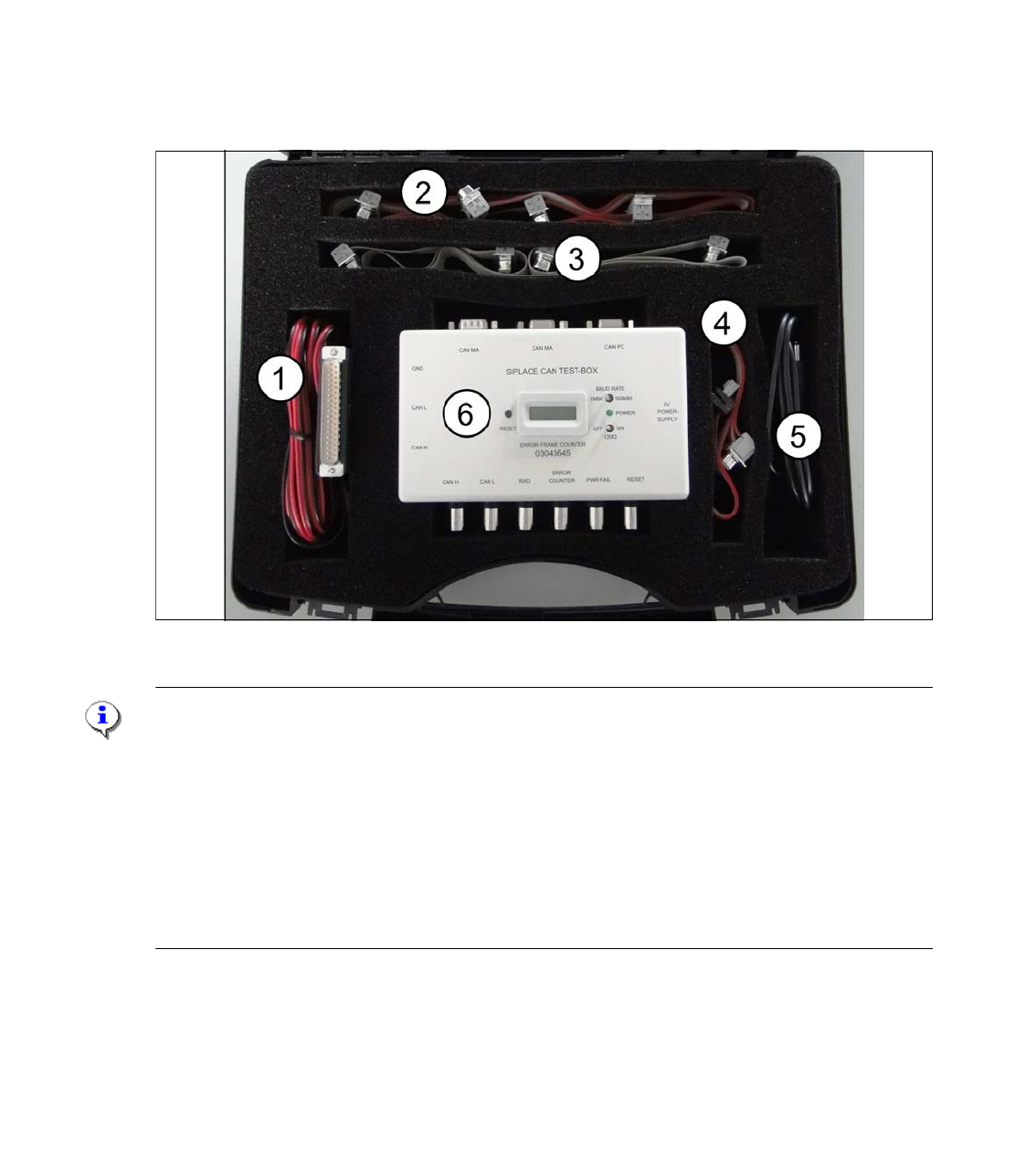
Ordernumber Siplace CAN Bus Analysis tool: 03105007-01
Content:
The following cables will be delivered with the ordernumber of the Siplace CAN Bus analysis tool.
(1) 03050022-xx Cable 1 Power supply 5 V,
(2) 03050023-xx Cable 2 CAN Bus Test cable 1,5m,
(3) 03050024-xx Cable 3 CAN Bus Test cable 0,75m,
(4) 03050025-xx Cable 4 CAN Bus Test Cable with 10 pins e.g. Tyco-connector 0,5m.
(5) 03105577-xx USB Powersupply cable for the CAN Test Box
(6) 03043645-xx SIPLACE CAN Bus Test Box
Fig. 2.1 - 2 SIPLACE CAN Bus Analysetool 03105007-xx
Note:
The 5V power supply cable for the CAN Test Box is equipped with a 37 pin Sub-D connector. This
connector can connect on the axis board A362/A363 only. For the axis board A364 an adapter
card is necessary.
03051220-02 Adapter card for A364 or
03058164-01Universal adapter A364/A363/A362-V24
In general, the 5V power supply for the CAN Test Box, which are only necessary for the display of
the Error Frame Counter and his electronic, can realize via a standard power supply. (e.g. 5V po-
wer supply with USB hub 2.0 in our machine - 03053145-xx)
Additionally you can order the following CAN Test cable.
03159250-01 Test cable CAN Bus (Flat cable with Sub-D connector /socket and multi-pin connec-
tor)
1 - 13
Edition 10/2018 SIPLACE CAN Bus
13
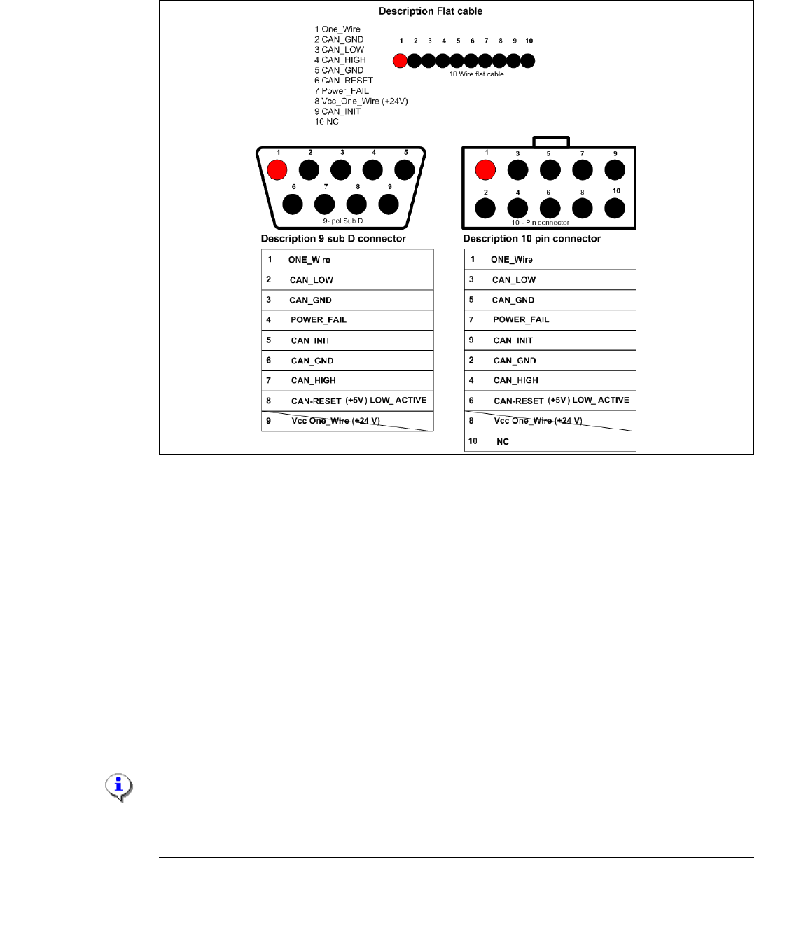
2.2 CAN Bus Signal Assignment
Fig. 2.2 - 1 Signal assignment at the different connectors
– CAN_INT – not in use (+5V)
– Power Fail – triggers recording of operating data at the placement head (+5V)
– CAN RESET – not in use (+5V) (HS50/60 use the signal for the Tape cutter and component
table)
– CAN HIGH - 2,5 +/– 0,3 V recessive level (machine in idle mode)
– CAN LOW - 2,5 +/– 0,3 V recessive level (machine in idle mode)
– CAN GND - Can bus ground
– Vcc 24V - for nozzle changers - no longer available after the above mentioned conversions
– One wire - only applies to HF series, in the machine CAN bus cable
Note:
Since the X-Series S and following (SX and TX), only the communication of the CAN bus takes
place via the CAN bus cable. That CAN_H and CAN_ L signal with CAN_GND, pin assignment
see picture above.