SA_MAES4S_en.pdf - 第12页
12 ! Attention! Decouple the carriage before move the carrige by hand . Damage the electronics! 1 2 4 5 6 2 3 Fig.8 Setting of the linear blade (Front view) Fig.9 Setting of the linear blade (Rear view) 1. Decouple the c…
11
4 Test and Change Device Parts
4.3 Changing the Linear Blade
Video
Video: MAESTRO 4S - Changing the linear blade on www.cab.de
!
Warning!
Risk of cutting injury in handling of the linear blade.
Risk of hand injury !
Wear protective gloves while changing the blade.
x
z
y
x
z
y
3
4
2
1
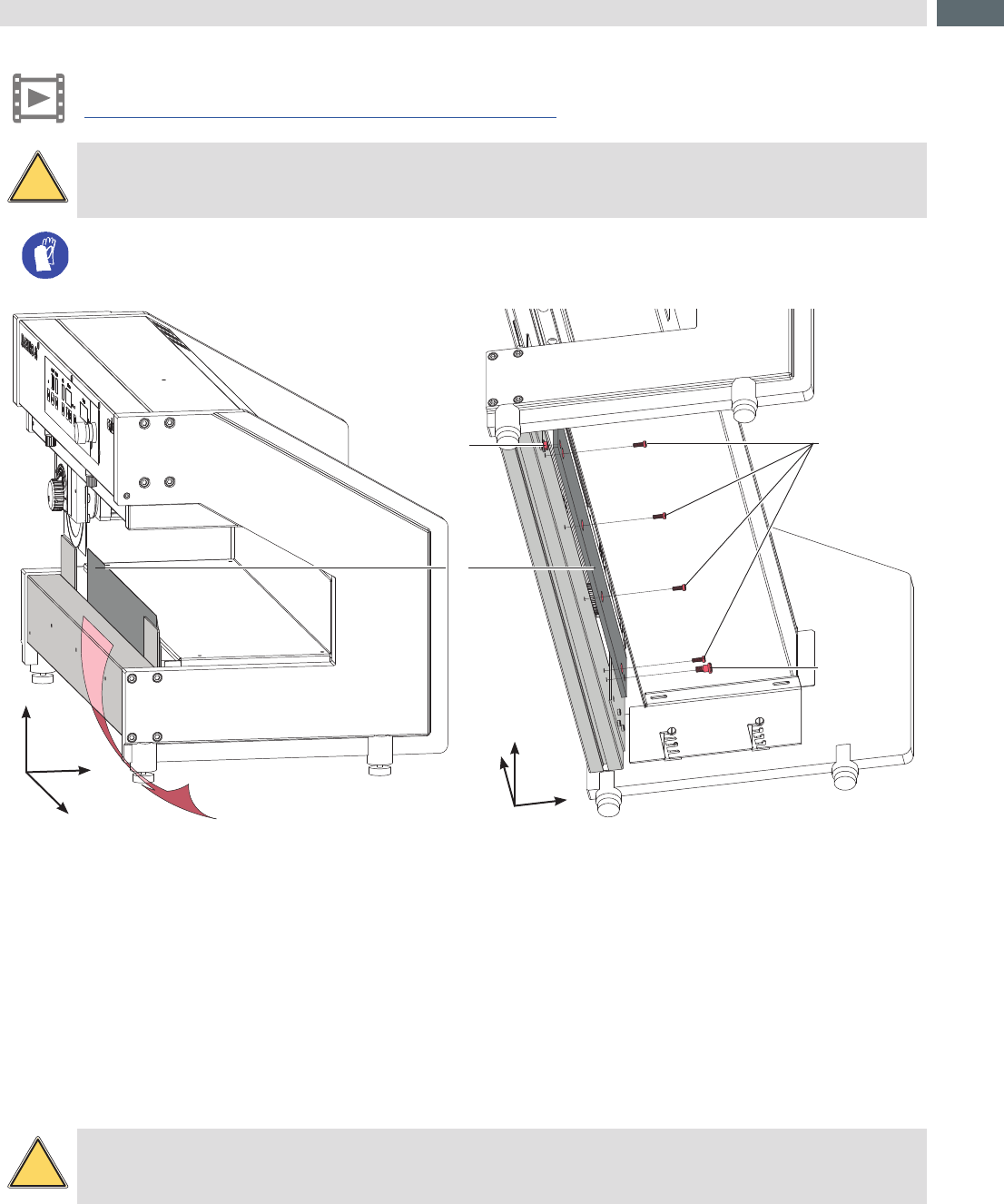
Fig.6 Changing the linear blade
(Front view - inclined)
Fig.7 Changing the linear blade
(Bottom view - inclined)
1. Loosen shouldered screw (4).
2. Hold the linear blade (1) to avoid an uncontrolled fall of the blade.
3. Loosen screws (3) . The eccentric (2) will used for guiding and will not loosened .
4. Pull out the linear blade (1) in direction of the device rear side from eccentric (2).
5. Move out the linear blade (1).
6. Mounting of the new linear blade in revers order.
4.4 Adjusting the Linear Blade
!
Warning!
Risk of cutting injury in handling of the linear blade.
To ensure a constant cutting quality and to prevent damaging of the blades must adjust the linear blade so that the
distance between upper blade and linear blade is constant of the full cutting length.
12
!
Attention!
Decouple the carriage before move the carrige by hand . Damage the electronics!
1 2 4 5 6
2
3
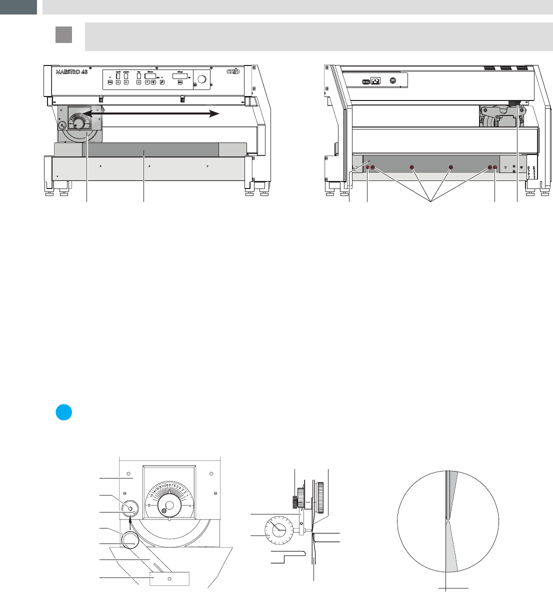
Fig.8 Setting of the linear blade (Front view) Fig.9 Setting of the linear blade (Rear view)
1. Decouple the carriage (1) from motor by the lever (3).
2. Turn upward the upper blade by the setting knob on the carriage (1).
3. Pull the carriage (1) over the full cutting length. The Distance between upper blade and linear blade (2) must be
constant over the full length.
4. Repeat this activity with reduced distance between upper blade and linear blade (2) up to a possible variation in
the distance is visible.
5. Are variation in the distance visible, loosen screws (5) .
6. Turn the eccentric (4) to adjust the linear blade (2).The shouldered screw (6) are the axle of rotation and by
turning the eccentric (4) will the linear blade (2) lifted or put down.
7. Repeat the setting and check up to the distance is over the full cutting distance the same.
8. Tighten screws (5).
4.5 Check the Blade Alignment
i
Notice!
When the machine is put into operation for the rst time, or following a move of equipment or a change of
blades, it is advantageous to re-check the alignment of the blades in relationship to one another. For this
purpose a dial gauge assembly (Part No. 8970208) is available as an option.
1
2
3
4
5
6
7
6
7
4
10
9
± 0,1
Roller Blade 8930509.001
FR4
Fig.10 Check the blade alignment
1. Move the blade carrier (1) to the middle of its range of travel.
2. Afxthedialgaugeassemblyontothethreadedhole(2)inthebladecarrierandscrewtightwiththeknurled
screw (4) provided. Ensure that the small spigot (5) mounted on the inside of the lever (6) locates correctly into
the hole (3) provided in the blade carrier.
3. Swing the lever (6) upwards until the tip of the gauge feeler (7) presses onto the upper blade (9) at 2 mm of the edge of
the blade. Rotate the scale on the dial gauge until the pointer in the 1/100 mm division is lined up with the „0“ on the scale.
4. Swing the lever (6) downwards until the tip of the gauge feeler (7) presses onto the lower blade (10) at 2 mm of
the edge of the blade.
5. In the event of the values obtained by the above procedure being greater than the values , the servicing agent
responsible for your machine should be contacted.
6. Remove the dial gauge assembly.
4 Test and Change Device Parts
13
4.6 Changing the hub to main motor
Danger!
Danger to life and limb from power supply.
Befor open the device unlink the power!
4 5 6 7 8 9 121110
1
2
3
13a 13b
rear view
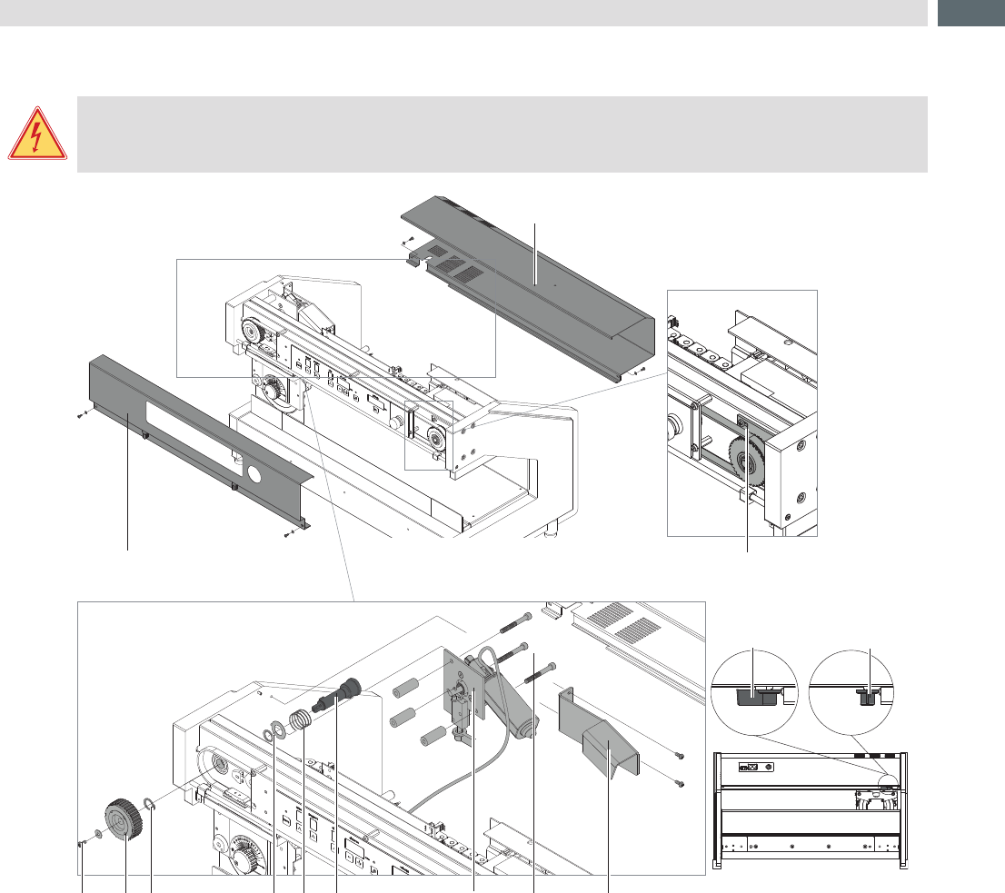
Fig.11 Dismount the hub to the main motor
1. Swing lever (13) in position b to connect the blade with the motor and to relax spring (8) .
2. Dismount front (1) and rear (2) cover.
3. Loosen the three screws (3) and move the tension wheel (5) to the center to relax the belt.
4. Loosen screw (4) and remove the belt gear (5) .
5. Dismount cooling bracket (12) .
6. Remover motor assembly (10) after loosening screws (11) .
7. Remove snap ring (6) with a snap ring caliper.
8. Pull out the hub (9) with spring (8), washer and snap ring (7) .
9. Remove snap ring (7) with a snap ring caliper and remove washer and spring (8) .
Mounting the new hub in reverse order.
4 Test and Change Device Parts