SA_MAES4S_en.pdf - 第9页
9 4 T est and Change Device Parts 4.1 Changing the Upper Blade Incaseofwasting,damageormaterialmodiedit'snecessarytochangetheupperblade. Video Video: MAESTRO 4S - Changing the upper blade on www .cab.…
8
3 Overview
3.2 Tools
Do not use any worn of damaged tools.
Only use tools and testing devices that are suitable for the task at hand.
Special tools (cab production):
• Dial gauge assembly (cab part No. 8970208) to check the blade position
Commercial tools:
• Allen key 1,5, 2,0, 2,5, 5,0 mm
• Jaw wrench 5,5 mm
• Phillips-head screwdriver, size 1
• Precision Snap Ring Caliper A0
• Precision Snap Ring Caliper A1
• Oscilloscope
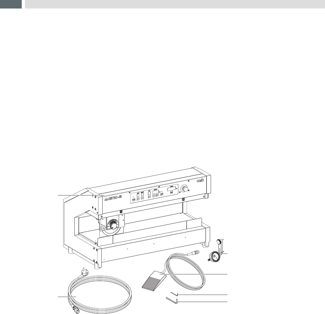
3.3 Contents of Delivery
5
6
4
2
1
3
1 Maestro 4S/300 (600)
2 Power Cable
3 Dial Gauge Assembly
4 Food Switch
5 Hexagonal Wrench
DIN911 2mm
6 Hexagonal Wrench
DIN911 5mm
Documentation
Fig.3 Contents of Delivery
9
4 Test and Change Device Parts
4.1 Changing the Upper Blade
Incaseofwasting,damageormaterialmodiedit'snecessarytochangetheupperblade.
Video
Video: MAESTRO 4S - Changing the upper blade on www.cab.de
Risk of hand injury !
Wear protective gloves while changing the blade.
Danger!
Risk of cutting damage by rotating blade!
Unlink device before you start service work!
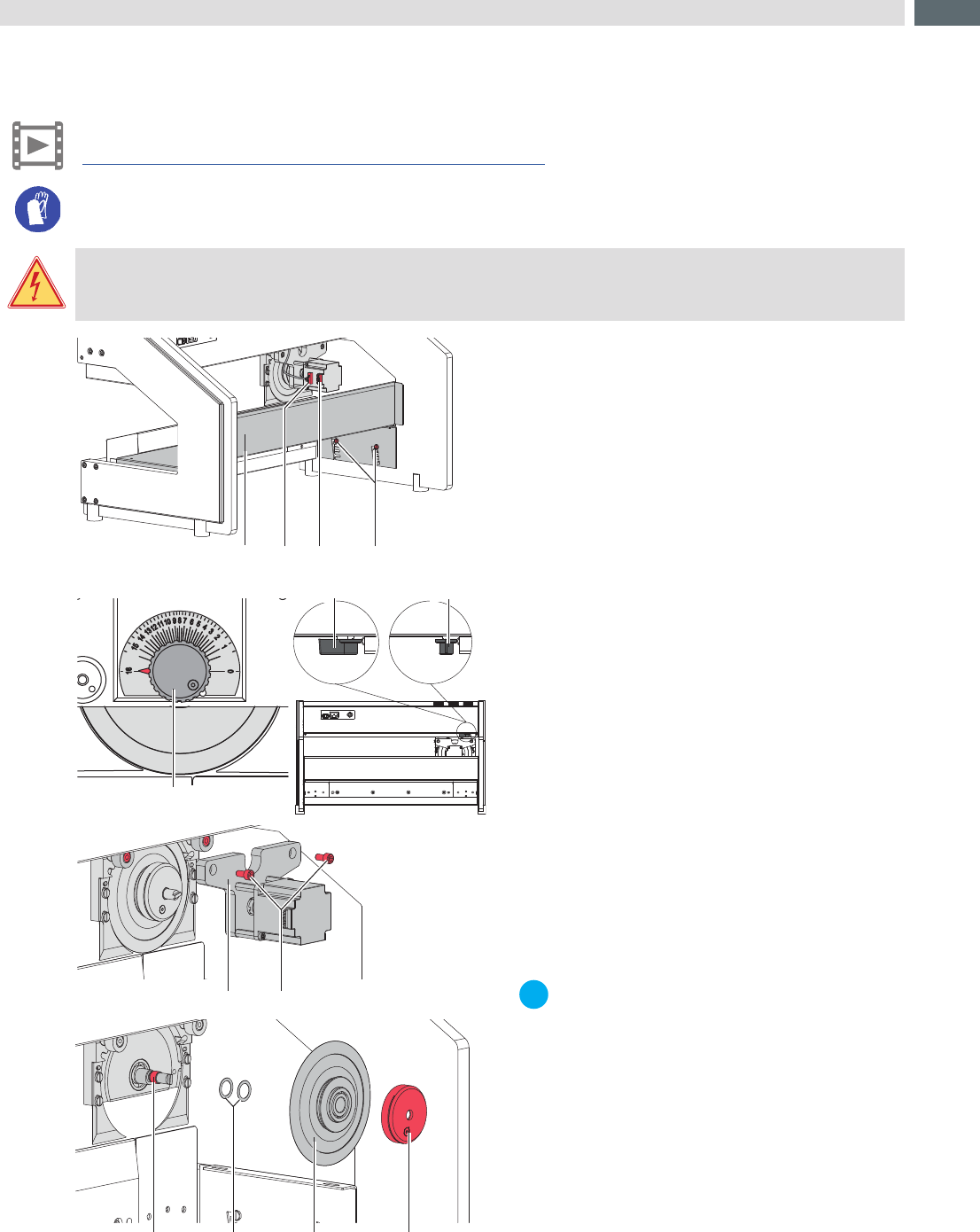
1
2 3 4
87
1211109
5
6
6
Fig.4 Changing the upper blade
1. After switching off the device and unlinking from
power supply, pull connector (2) out from female
connector (3) on the motor.
2. Slide the carriage to the left end position (front view).
Like upper picture.
3. Set the setting knob (5) on value 16 - blade on the
highest position.
4. Swing lever (6) in position a to release.
5. Loosen screws (4) and remove table (1) by
movements back and top.
6. Loosen screws (8).
7. Remove motor carriage with mounted motor (7).
8. Hold the setting knob (5) and loosen the knurled
nut(12) .
9. Remove blade (11) . It's possible that the washer
(10) are adhere on the blade.
Remove the Washer (10) from blade and take it back
on the axle (9).
10. Take the new blade (11) on the axle (9).
11. Hold the setting knob (5) and tighten the knurled
nut(12) .
12. Set the setting knob (5) on value 16.
13. Mount motor carriage with mounted motor (7), check
the connection of the coupling motor/axle and tighten
screws (8) .
14. Swing lever (6) in position b to couple.
15. Hang up the table (1) and tighten screws (4) .
16. Put in connector (2) into female connector (3) on the
motor.
i
Notice!
Adjust the stopper of the upper blade
before you start operation. chapter 4.2
10
4.2 Adjustment of the Upper Blade Stopper
i
Notice!
The lower stop of the upper blade adjustment is already adjusted by delivery.
After a long operation time, while working at strongly varying temperatures or else after replacing a
blade, it is recommended to re-adjust the lower stop.
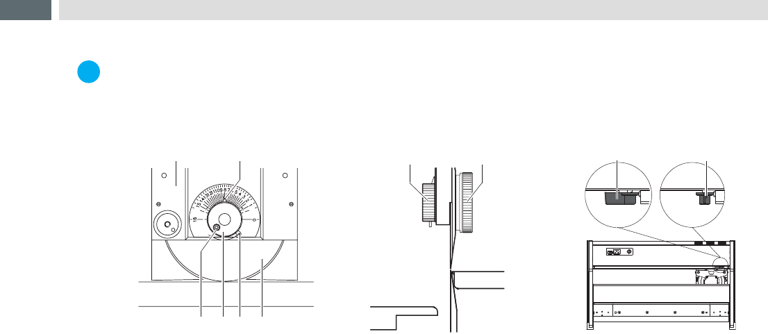
3 5 6
1 2
4
74
Fig.5 Adjustment of the upper blade stopper
1. Move the lever (8) to the position 'a'. The motor drive to the blade carrier (1) is now disconnected.
2. Rotate the pointer (2) with the knob (4) counterclockwise to position "16".
3. Move the upper blade carrier (1) in the middle position of the lower blade.
4. Loosen the screw (3).
5. Move the knob (4) clockwise until the upper and lower blades are in a distance of 0.03 mm. Use a thickness
gauge.
6. Swing the strut (5) clockwise until you reach the stop and tighten the screw (3). This adjustment locks the upper
blade in place to prevent it from moving out of adjustment.
7. Move the lever (8) to the position 'b'. The motor drive to the blade carrier (1) is now reconnected.
4 Test and Change Device Parts